
Lambda sensor
- Make
- Alfa Romeo
- Model
- GTV / Spider GTV and Spider (916) Factory Service Manual
- Year
- 1995–2000
- Section
- Exhaust system › Lambda sensor
LAMBDA SENSOR
The exhaust system is equipped with two "planar" lambda sensors fitted on the front section of the exhaust pipe.
One lambda sensors controls the right-hand combustion (cylinders 1 - 2 - 3) while the other controls the left-hand side combustion (cylinders 4 - 5 - 6). The injection ECU identifies the mixture compositions (lean or rich) according to the lambda sensor output voltage.
The ECU adjusts the amount of injected fuel to ensure optimal composition of the mixture (λ = 1), to create ideal conditions for the treatment of exhaust fumes in the catalytic converter.
If the mixture is too rich (λ < 1) the amount of fuel is reduced and if the mixture is too lean (λ > 1) the amount of fuel is increased.
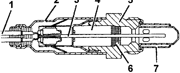
- Connection wire
- Protective sleeve
- Planar sensor element
- Ceramic supporting tube
- Sensor seat
- Ceramic seal
- Protection pipe
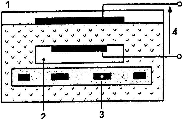
The measuring cell and the heater and built-into the "planar" ceramic element (layered) with the advantage of rapid cell heating to allow a "closed loop" control (λ = 1) within 10 seconds from when the engine is started.
- Exhaust fumes
- Reference air passage
- Heater
- Lambda sensor voltage
The lambda sensor operation is based on the principle of a oxygen concentration cell and solid electrolyte. The surfaces of the measuring cells are covered with noble material micro-pore layers.
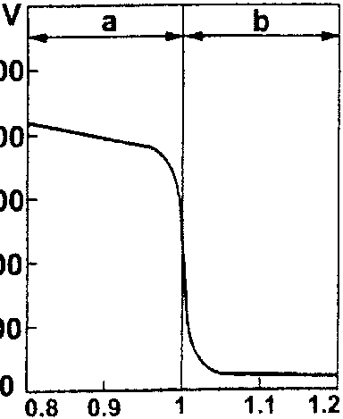
The lambda sensor, in contact with the exhaust fumes, generates an electrical signal with a voltage which varies according to the concentration of oxygen in the fumes.
The voltage is characterised by a sudden variation with the composition of the mixture differs from λ = 1.
The lambda sensor heating is governed by the injection ECU proportionally according to exhaust fume temperature.
This avoids thermal shocks to the ceramic casing due to the contact with condensed water in the exhaust fumes when the engine is cold.
Parts & tools for this job For 1995 Alfa Romeo GTV / Spider
- PARTOxygen sensorSearch: Alfa Romeo GTV / Spider 1995 oxygen sensor
- TOOLOxygen sensor socketSearch: oxygen sensor socket
- TOOLOBD2 scannerSearch: OBD2 scanner
Links open Amazon search results in a new tab. As an Amazon Associate I earn from qualifying purchases.