
A1
| Overview - electronic stabilisation program |
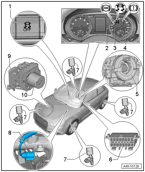
| 1 - | ESP button |
| q | Removing and installing → Removing and installing buttons in dash panel; Rep. gr.96 |
| 2 - | ABS warning lamp -K47- |
| Function of warning lamp → Chapter |
| 3 - | ESP warning lamp -K155- |
| Function of warning lamp → Chapter |
| 4 - | Brake system warning lamp -K118- |
| Function of warning lamp → Chapter |
| 5 - | Steering angle sender -G85- |
| q | Steering column electronics control unit -J527- incorporates airbag coil connector and return ring with slip ring -F138- and steering angle sender -G85- → Rep. gr.94 |
| q | Removing and installing → Chapter |
| 6 - | Diagnostic connector |
| q | Fitting location: cover in driver's footwell |
| 7 - | Speed sensor |
| q | Front right -G45- |
| q | Front left -G47- |
| q | Rear right -G44- |
| q | Rear left -G46- |
| q | Can be checked in „Guided Fault Finding“ using vehicle diagnostic, testing and information system -VAS 505 x- or -VAS 505 x- |
| q | Exploded view → Chapter |
| 8 - | Brake light switch -F - |
| q | Location: on brake master cylinder |
| q | Can be checked in „Guided Fault Finding“ routine using vehicle diagnostic, testing and information system -VAS 505 x- |
| Can be re-installed if removed |
| q | Removing and installing → Chapter |
| 9 - | ABS control unit -J104- |
| q | With integral lateral acceleration sender -G200-, yaw rate sender -G202- and longitudinal acceleration sender -G251- |
| q | Hydraulic unit and control unit together form the hydraulic control unit. |
| q | Do not unplug connector before completing self-diagnosis. Switch off ignition before detaching connector. |
| q | Fitting location: on hydraulic unit in engine compartment (bottom right) |
| q | Removing and installing (vehicles with petrol engine) → Chapter |
| q | Removing and installing (vehicles with 1.4 ltr. TSI engine) → Chapter |
| q | Removing and installing (vehicles with TDI engine) → Chapter |
 Note
Note| On vehicles with TDI engine the diesel particulate filter must be removed. |
Note| The ABS control unit -J104- must not be separated from the ABS hydraulic unit -N55-. |
| 10 - | ABS hydraulic unit -N55- |
| q | Hydraulic unit and control unit together form the hydraulic control unit. |
| q | Do not unplug connector before completing self-diagnosis. Switch off ignition before detaching connector. |
| q | Fitting location: on hydraulic unit in engine compartment (bottom right) |
| q | Removing and installing (vehicles with petrol engine) → Chapter |
| q | Removing and installing (vehicles with 1.4 ltr. TSI engine) → Chapter |
| q | Removing and installing (vehicles with TDI engine) → Chapter |
Note| On vehicles with TDI engine the diesel particulate filter must be removed. |
Note| The ABS control unit -J104- must not be separated from the ABS hydraulic unit -N55-. |
|