
A1
 WARNING
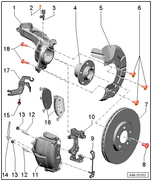
| 1 - | Wheel bearing housing |
| 2 - | Bolt |
| q | 9 Nm |
| 3 - | Speed sensor |
| q | Before inserting sensor, clean inner surface of fitting hole and coat with high-temperature paste -G 052 112 A3- |
| 4 - | Wheel bearing unit with rotor |
| q | Removing and installing → Rep. gr.40 |
| 5 - | Splash plate |
| q | Removing and installing → Chapter |
| 6 - | Bolt for splash plate |
| q | 12 Nm |
| 7 - | Brake disc |
| q | Wear limit → Chapter |
| q | To remove, unbolt brake caliper housing |
| q | Do not force brake discs off wheel hub; if necessary, use rust remover, otherwise brake discs could be damaged. |
| q | Always renew on both sides of axle |
| q | Removing and installing → Chapter |
| 8 - | Bolt for brake disc |
| q | 5 Nm |
| 9 - | Retaining spring |
| q | Insert in both holes in brake caliper housing |
| 10 - | Brake carrier |
| q | Replacement carriers are supplied assembled and with sufficient grease on guide pins |
| q | Renew protective caps if they have been damaged (repair kit); use grease sachet supplied to lubricate the guide pins |
| 11 - | Brake caliper |
| q | Unscrew from brake carrier to renew brake pads |
| q | Servicing → Chapter |
| q | If assembly work is required, do not leave caliper hanging from brake hose but secure it to body with wire |
| q | The only permissible brake caliper repair operations are „Renewing brake pads“ and „Servicing front brake caliper“ |
| q | Do not twist brake hose when installing |
| q | Removing and installing → Chapter |
| q | Renewing → Chapter |
| 12 - | Guide pin |
| q | 30 Nm |
| 13 - | Protective cap |
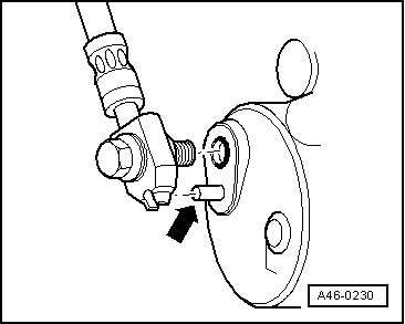
| 14 - | Brake hose |
| q | With locating element |
| q | Do not twist hose when installing |
| Make sure the brake hose is routed correctly. The brake hose must not be kinked or crushed or chafe against the body at any point |
| q | 35 Nm |
 Note
Note| Make sure groove in banjo union of brake hose is fitted on locating pin. |
| 15 - | Bolt |
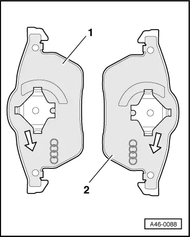
| 16 - | Brake pads |
| q | Wear limit → Chapter |
| q | With wear indicator (left-side only) |
Note| An electrical wire for the pad wear indicator is fitted to the left-side inner pad. |
| q | Remove any adhesive foil from backplate before inserting |
| q | Checking pad thickness → Booklet808 |
| q | Before fitting pads, clean guide surfaces and apply a thin coating of polycarbamide grease → Parts catalogue |
| q | Always renew on both sides of axle |
| q | Removing and installing → Chapter |
| q | Note installation position → Fig. |
| 17 - | Bracket |
| 18 - | Bolt |
| q | 125 Nm |
Note
Note |
|
|
|