
A1
|
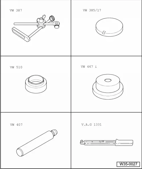
| Special tools and workshop equipment required |
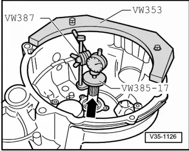
| t | Universal dial gauge bracket -VW 387- |
| t | End measuring plate -VW 385/17- |
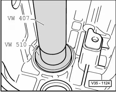
| t | Thrust pad -VW 510- |
| t | Thrust plate -VW 447 i- |
| t | Press tool -VW 407- |
| t | Torque wrench -V.A.G 1331- |
| t | Dial gauge |
|
|
|
 Note
Note
|
|
Note
|
|
| Bearing clearance (measured value) | Thickness of shim according to table |
| 1.21 mm | 1.175 mm |
|
| Bearing clearance | Shim |
| Measured value (mm) | Thickness (mm) |
| 0.671…0.699 0.700…0.724 0.725…0.749 | 0.650 0.675 0.700 |
| 0.750…0.774 0.775…0.799 0.800…0.824 | 0.725 0.750 0.775 |
| 0.825…0.849 0.850…0.874 0.875…0.899 | 0.800 0.825 0.850 |
| 0.900…0.924 0.925…0.949 0.950…0.974 | 0.875 0.900 0.925 |
| 0.975…0.999 1.000…1.024 1.025…1.049 | 0.950 0.975 1.000 |
| 1.050…1.074 1.075…1.099 1.100…1.124 | 1.025 1.050 1.075 |
| 1.125…1.149 1.150…1.174 1.175…1.199 | 1.100 1.125 1.150 |
| 1.200…1.224 1.225…1.249 1.250…1.274 | 1.175 1.200 1.225 |
| 1.275…1.229 1.300…1.324 1.325…1.349 | 1.250 1.275 1.300 |
| 1.350…1.374 1.375…1.399 1.400…1.424 | 1.325 1.350 1.375 |
| 1.425…1.449 1.450…1.474 1.475…1.499 | 1.400 1.425 1.450 |
| 1.500…1.524 1.525…1.549 1.550…1.574 | 1.475 1.500 1.525 |
| 1.575…1.599 1.600…1.624 1.625…1.649 | 1.550 1.575 1.600 |
| 1.650…1.674 1.675…1.699 1.700…1.724 | 1.625 1.650 1.675 |
Note
|