
A1
| Exploded view - dismantling and assembling input shaft |
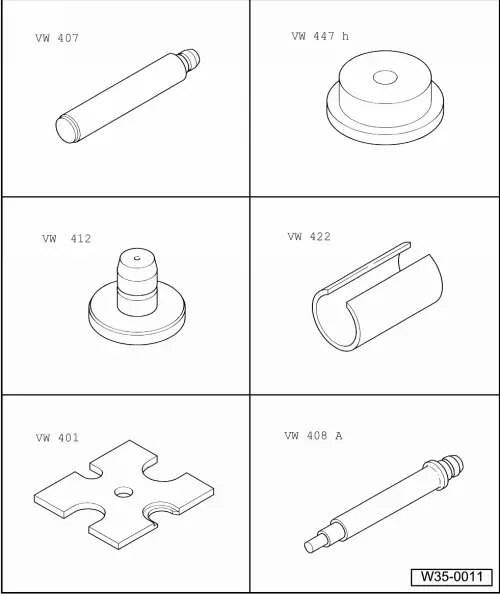
| Special tools and workshop equipment required |
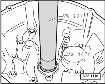
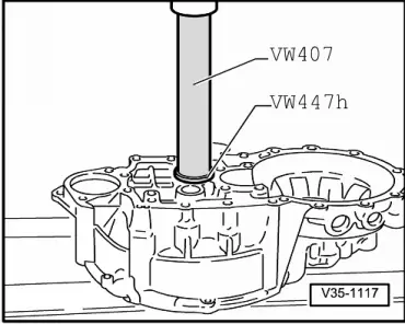
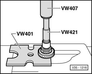
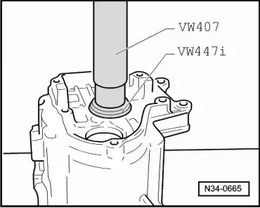
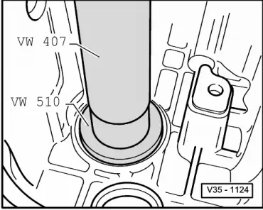
| t | Press tool -VW 407- |
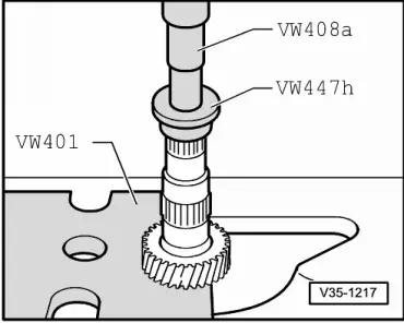
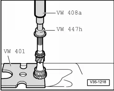
| t | Thrust plate -VW 447 H- |
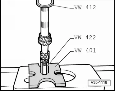
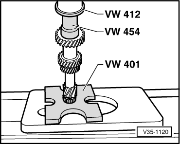
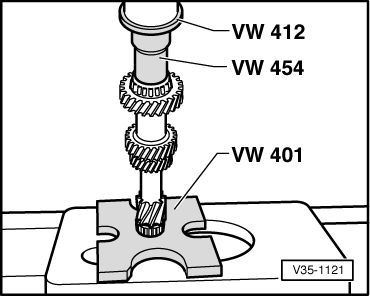
| t | Press tool -VW 412- |
| t | Tube -VW 422- |
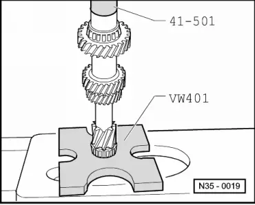
| t | Thrust plate -VW 401- |
| t | Thrust plate -VW 402- |
| t | Press tool -VW 408 A- |
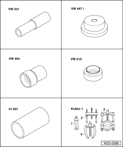
| t | Tube -VW 421- |
| t | Press tool -VW 454- |
| t | Thrust plate -VW 447 i- |
| t | Thrust pad -VW 510- |
| t | Drift sleeve -41-501- |
| t | -3-Splitter -Kukko 17/1- |
 Note
Note| t | When fitting new gear wheels or input shaft, refer to technical data → Chapter and → Electronic parts catalogue. |
| t | The input shaft must be re-adjusted if the position of tapered roller bearings is affected when renewing parts. Refer to table of adjustments → Chapter. |
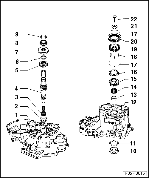
| 1 - | Clutch housing |
| 2 - | Tapered roller bearing outer race |
| q | Pressing out → Fig. |
| q | Pressing in → Fig. |
| 3 - | Tapered roller bearing inner race |
| q | Pressing off → Fig. |
| q | Pressing on → Fig. |
| 4 - | Input shaft |
| q | Adjusting → Chapter |
| 5 - | 3rd gear wheel |
| q | Installation position: Collar faces 4th gear |
| q | Pressing off → Fig. |
| q | Pressing on → Fig. |
| 6 - | Circlip |
| q | Always renew |
| 7 - | 4th gear wheel |
| q | Pressing off with tapered roller bearing outer race and sleeve → Fig. |
| q | Pressing on → Fig. |
| q | Shoulder faces towards 3rd gear |
| 8 - | Tapered roller bearing inner race |
| q | Pressing off with 4th gear wheel and sleeve → Fig. |
| q | Pressing on → Fig. |
| 9 - | Thrust washer |
| 10 - | Tapered roller bearing outer race |
| q | Pressing out → Fig. |
| q | Pressing in → Fig. |
| 11 - | Shim |
| q | Determining thickness → Chapter |
| 12 - | Gearbox housing |
| 13 - | Sleeve |
| q | For needle bearing |
| q | Press off with 4th gear wheel and tapered roller bearing inner race → Fig. |
| q | Pressing on → Fig. |
| q | Fit thrust washer → Item before installing |
| 14 - | Needle bearing |
| 15 - | 5th speed selector gear |
| q | Pull off together with 5th gear synchro-hub → Chapter |
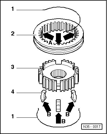
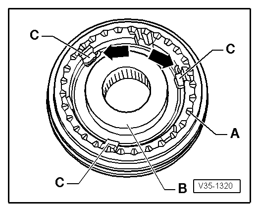
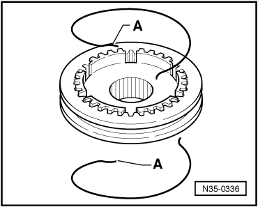
| 16 - | 5th gear synchro-ring |
| q | With cast locking pieces → Fig. |
| q | Checking for wear → Fig. |
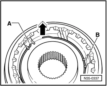
| 17 - | Spring |
| q | Offset version → Fig. |
| q | Installation position → Fig. |
| 18 - | Locking pieces (3x) |
| q | Installation position → Fig. |
| 19 - | 5th gear synchro-hub |
| q | Pulling off individually → Chapter |
| q | Pulling off together with gearbox housing → Chapter |
| q | Dismantling and assembling → Fig. |
| 20 - | 5th gear locking collar |
| q | Removing and installing → Chapter |
| 21 - | Dished spring |
| q | Installation position → Fig. |
| 22 - | Bolt |
| q | Tightening torque → Item |
| q | Always renew |
| q | Fitted piece on bolt head holds dished spring in position → Fig. |
|
|
|
|
|

|
|
|
|
|
|
|
|
|
|
|
|
|
|
|
|
|
|
|
|
|
|
|
|
|