audi Workshop Repair Guides

Audi Workshop Service and Repair Manuals

Renewing bearing mounting with grooved ball bearings for input and output shafts > < Exploded view - input shaft, output shaft, differential, selector mechanism and selector forks
Assembly sequence - removing and installing input shaft, output shaft and differential
   
Assembly sequence - removing and installing input shaft, output shaft and differential
Special tools and workshop equipment required
t  Thrust plate -VW 401-
t  Thrust plate -VW 402-
t  Press tool -VW 407-
t  Press tool -VW 412-
t  Tube -VW 422-
t  Guide pin -T10079-

   
t  Thrust piece -T10080-
t  Thrust piece -T10081-
t  Thrust block -T10083-
t  Thrust plate -T10084 A-
t  Thrust piece -T10085-

   
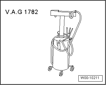
t  Used oil collection and extraction unit -V.A.G 1782-
  W00-10211
Dismantling gearbox
l  Gearbox removed
–  Mount gearbox on assembly stand → Chapter.
–  Place used oil collection and extraction unit -V.A.G 1782- below gearbox.
–  Drain off gear oil.
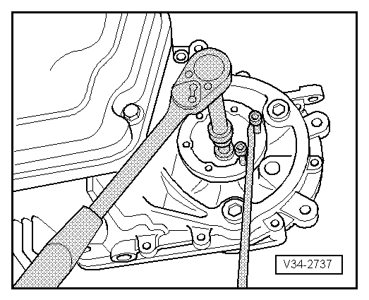
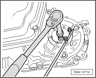
–  Remove left flange shaft securing bolt; to do so, screw two bolts into flange and counterhold flange shaft with tyre iron or other suitable lever.
–  Pull out flange shaft together with spring, thrust washer and tapered ring.
  V34-2737
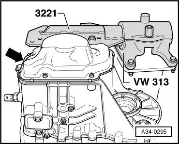
–  Unbolt gearbox housing cover -arrow-.
  A34-0295
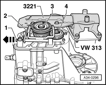
–  Pull out pivot pin -1- for 5th gear selector fork -2- and remove selector fork.
–  Remove circlip -3- for 5th gear synchronising hub.
–  Remove circlip -4- for 5th gear wheel.
–  Take off synchronising hub for 5th gear, selector gear and 5th gear wheel.
  A34-0296
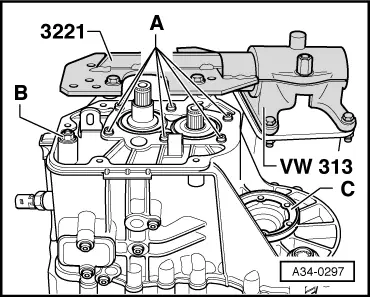
–  Unscrew securing bolts -A- for bearing mounting for input and output shafts.
–  Unscrew hexagon flange nut -B- for selector mechanism (reverse gear wheel mounting).
–  Remove securing bolt for flange shaft (left-side); to do so, screw two bolts into flange and counterhold flange shaft with tyre iron or other suitable lever.
–  Pull out flange shaft -C- together with spring, thrust washer and tapered ring.
  A34-0297
–  Turn gearbox on assembly stand so that clutch housing faces upwards.
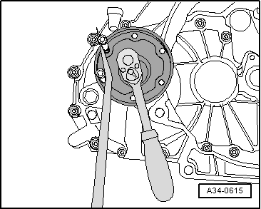
–  Remove securing bolt for flange shaft (right-side); to do so, screw two bolts into flange and counterhold flange shaft with tyre iron or other suitable lever.
–  Pull out flange shaft together with spring, thrust washer and tapered ring.
  A34-0615
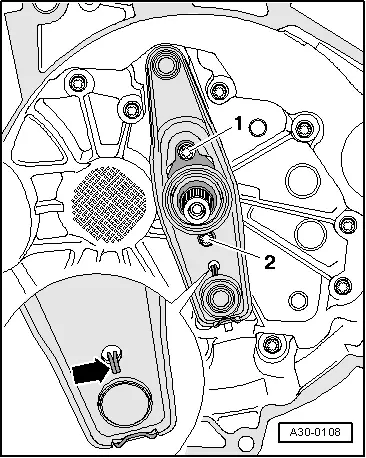
–  Unhook spring -arrow- from clutch release lever.
–  Remove bolts -1- and -2-.
–  Remove release lever with release bearing and guide sleeve.
  A30-0108
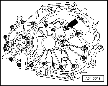
–  Remove all 18 bolts -arrow- securing clutch housing.
–  Carefully remove clutch housing by levering alternately at the protruding webs on the housing, taking care not to damage the sealing surfaces.
  Caution
Make sure you keep clutch housing straight to avoid damaging roller bearings and bearing seat on input and output shafts.
  A34-0619
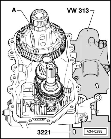
–  Remove differential -A- from gearbox housing.
  A34-0298
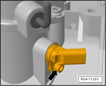
–  Gearbox for vehicles with start/stop system: remove gearbox neutral position sender -G701--arrow-.
  N34-11289
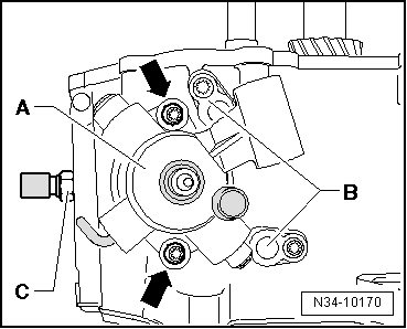
–  Remove selector shaft with selector mechanism cover -A-. For this purpose, bring selector shaft into the neutral position. Then remove bolts -arrows- and pull selector mechanism cover and selector shaft out of gearbox housing.
–  Remove pivot pins -B- from top of gearbox.
–  Remove reversing light switch -F4--C-.
  N34-10170
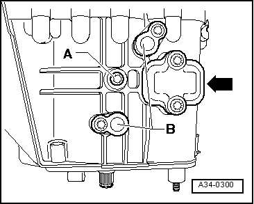
–  Remove bolt -A- securing reverse gear shaft.
–  Remove pivot pins -B- from gearbox underside.
  Note
Do not remove cover plate -arrow- when dismantling gearbox.
  A34-0300
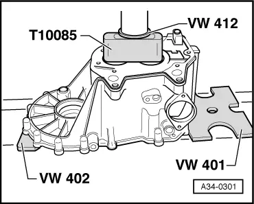
–  Press out input and output shafts together with bearing mounting, selector mechanism (selector forks) and reverse gear wheel.
  Note
t  Place gearbox housing on thrust plates -VW 401- and -VW 402- so that the dowel sleeves in the gearbox housing do not become damaged.
t  Make sure components do not drop out when being removed (get help from a second person if necessary).
  A34-0301
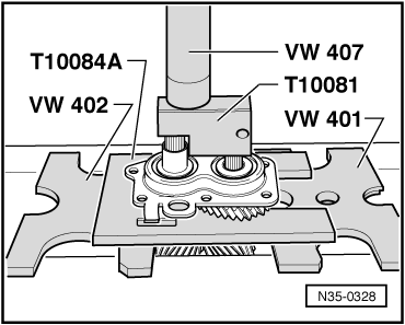
–  Press input and output shaft out of bearing mounting and grooved ball bearings ⇒ page → Chapter.
  Note
The bearing mounting must always be renewed if it is separated from the gearbox housing.
  N35-0328
Assembling gearbox
Tightening torques → Chapter, → Chapter, → Chapter
l  Bearing mounting with grooved ball bearings has been renewed → Chapter
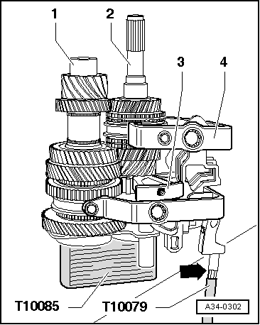
–  Place the pre-assembled input shaft -2- and output shaft -1- with bearing mounting for grooved ball bearings in thrust piece -T10085-.
–  Insert selector mechanism (selector forks) -4- in locking collars on shafts.
–  Fit reverse gear shaft -3- with reverse gear wheel.
–  Screw guide pin -T10079- onto threaded pin (reverse gear mounting) -arrow-.
  A34-0302
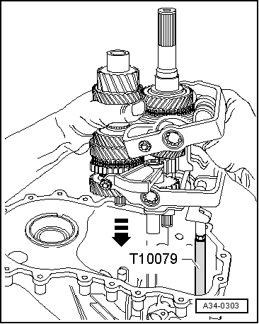
–  Insert assembled components into gearbox housing, running guide pin -T10079- into gearbox housing through hole for selector mechanism mounting.
–  Unscrew guide pin -T10079-.
–  Check that selector forks engage correctly in locking collars before pressing in bearing mounting.
  A34-0303
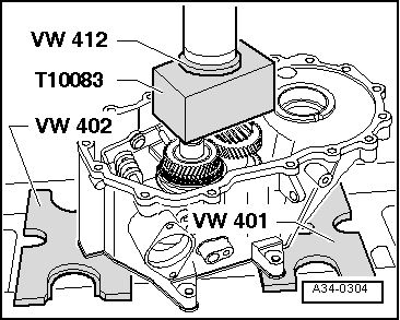
–  Carefully press in bearing mounting together with input and output shafts as far as the stop.
–  Secure bearing mounting lightly with bolt tightened finger-tight.
  A34-0304
–  Screw in bolt -A- for reverse gear shaft.
–  Install pivot pins -B- on underside of gearbox.
  A34-0300
–  Install reversing light switch -F4--C-.
–  Align selector mechanism and install pivot pins -B- on top of gearbox.
–  Set selector plates in neutral position.
–  Clean sealing surfaces; they must be free from oil and grease.
–  Apply sealing paste -AMV 188 200 03- evenly to sealing surface.
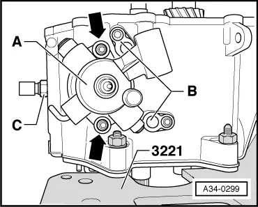
–  Install selector shaft with selector mechanism cover -A-. Then tighten bolts -arrows-.
  A34-0299
–  Gearbox for vehicles with start/stop system: fit gearbox neutral position sender -G701--arrow- and tighten securing bolt to specified torque → Item.
  N34-11289
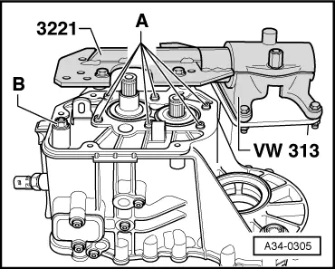
–  Using new bolts -A-, secure bearing mounting for input and output shafts.
  Note
Tighten the bolts in stages to the specified torque in diagonal sequence, starting in the centre.
–  Tighten hexagon flange nut -B- for selector mechanism (selector forks).
–  Engage all gears to check function.
  A34-0305
–  Install differential -A-.
–  Clean sealing surfaces; they must be free from oil and grease.
–  Apply sealing paste -AMV 188 200 03- evenly to sealing surface.
–  When installing housing, rotate input shaft by hand to enable bearing to slide easily onto its seat.
  A34-0298
–  Tighten gearbox housing bolts -arrow- diagonally in stages.
–  Turn gearbox on assembly stand so that gearbox housing faces upwards.
  A34-0619
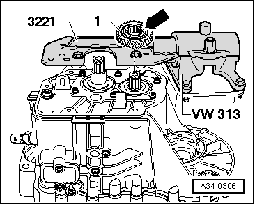
–  Fit 5th gear wheel -1-.
l  Installation position of 5th gear wheel: the large collar -arrow- points to the gearbox housing cover.
  A34-0306
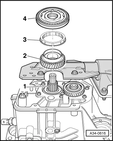
–  Install the following components in the sequence indicated:
1 - Needle bearing for 5th speed selector gear
2 - 5th speed selector gear
3 - 5th gear synchro-ring
4 - 5th gear synchronising hub with locking collar and check ring
  A34-0616
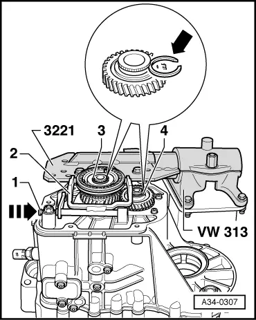
–  Fit 5th gear selector fork -2- and slide pivot pin -1- in onto stop in direction of -arrow-.
–  Determine thickness of new circlips -arrow- for input shaft -3- and output shaft -4-.
–  Determine the thickest circlip that will just fit and install it. For part number, refer to → Electronic parts catalogue.
The following circlips are available:
  A34-0307
Circlip thickness (mm)
2.002.102.20

   
–  Install gearbox housing cover -arrow-.
  A34-0295
–  Install both flange shafts with springs, thrust washers and tapered rings (press in towards gearbox housing and tighten bolts).
–  Install clutch release lever together with release bearing and guide sleeve → Chapter.
–  Fill up oil in gearbox and check oil level → Chapter.
  N34-10712

Renewing bearing mounting with grooved ball bearings for input and output shafts > < Exploded view - input shaft, output shaft, differential, selector mechanism and selector forks