| –
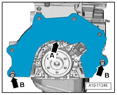
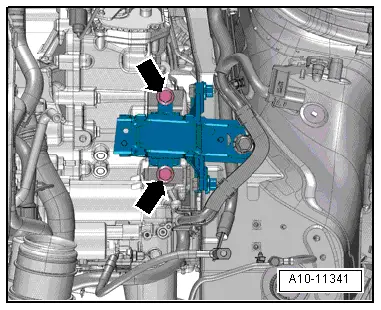
| Check that dowel sleeves -B- for centralising engine/gearbox are in the cylinder block; install any missing dowel sleeves. |

Caution | If the dowel sleeves -arrows B- are not fitted, this will lead to gear-change problems, clutch malfunction and in some cases gearbox noise (gears will make rattling noises). |
|
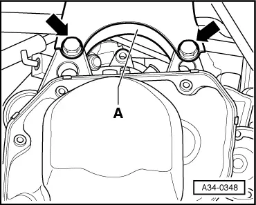
| –
| Make sure that the intermediate plate is engaged on the sealing flange -arrow A- and fitted on the dowel sleeves -arrows B-. |
| –
| Check clutch release bearing for wear and renew if necessary. |
| –
| Lubricate surface which contacts ball-head pin with MoS2 grease. |
| –
| Place engine and gearbox jack -V.A.G 1383 A- underneath vehicle. |
| l
| The arrow symbol on the adjustment plate points in the direction of travel. |
| –
| Remove flange shaft (right-side) when installing a new gearbox or exchange gearbox. |
| –
| Check oil seal for flange shaft (right-side) for leakage and renew if necessary → Chapter. |
|
|
|
 Note
Note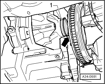
 WARNING