audi Workshop Repair Guides

Audi Workshop Service and Repair Manuals

Installing gearbox > < Adjusting selector mechanism
Removing gearbox
   
Removing gearbox
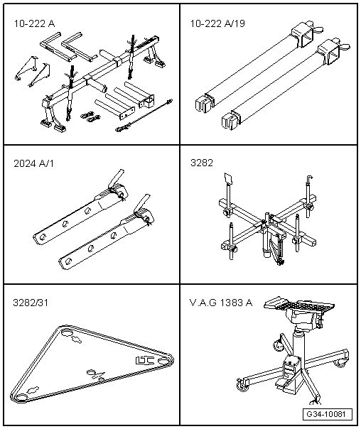
Special tools and workshop equipment required
t  Support bracket -10 - 222 A-
t  Adapter -10 - 222 A /19-
t  Hook -2024 A/1- from lifting tackle -2024 A-
t  Gearbox support -3282-
t  Adjustment plate -3282/31-
t  Engine and gearbox jack -V.A.G 1383 A-

   
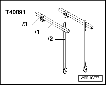
t  Engine support bracket, basic set -T40091-
Procedure
  Note
Re-attach all cable ties at the same locations when re-installing.
  W00-10277
  Caution
When disconnecting the battery there is a risk of serious damage to electronic components:
Observe the correct procedure for disconnecting the battery.
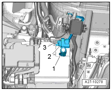
–  With ignition switched off, disconnect battery earth wire -1- and remove battery → Electrical system; Rep. gr.27.
  A27-10278
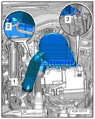
–  Remove air cleaner housing → Injection and ignition system; Rep. gr.24.
  A24-10737
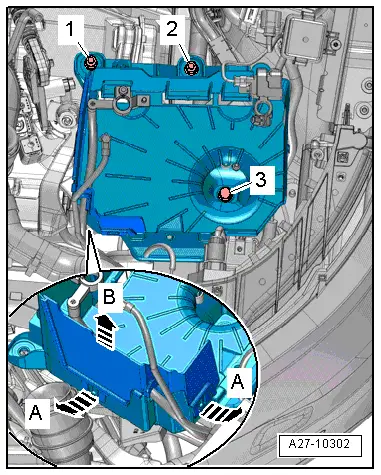
–  Release retainers -arrows A- and lift out side panel for battery tray -arrow B-.
–  Remove bolt -3- and nuts -1 and 2- and detach battery tray.
  A27-10302
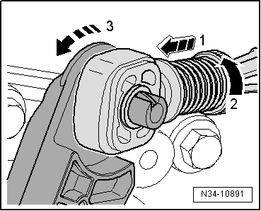
l  To avoid damage to the gate selector cable, the cable end-piece must be separated from the gate selector cable before removal.
–  Pull locking mechanism forwards -arrow 1- onto stop and then turn to left -arrow 2- to lock.
–  Push gate relay lever forwards in direction of -arrow 3-.
  N34-10891
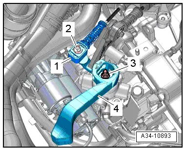
–  Remove securing clip -2-.
–  Pull gear selector cable -1- off gearbox selector lever -4-.
–  Remove nut -3- and detach gearbox selector lever.
  A34-10893
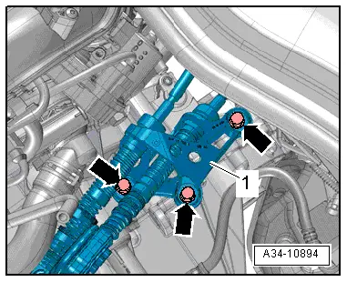
–  Unscrew bolts -arrows-, remove cable support bracket -1- and place to one side together with cables.
  A34-10894
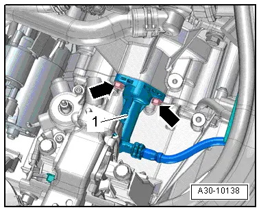
–  Remove bolts -arrows-, detach clutch slave cylinder -1- and place to one side. Do not disconnect pipes.
  Caution
Risk of irreparable damage to clutch slave cylinder.
Do not press clutch pedal after removing clutch slave cylinder.
  A30-10138
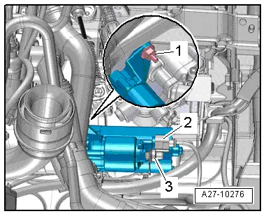
–  Unplug electrical connector -2-.
–  Detach cover for B+ wire -3-.
–  Remove nut and move B+ wire clear.
–  Remove bolt -1-.
  A27-10276
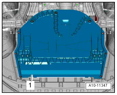
–  Remove noise insulation -1- → General body repairs, exterior; Rep. gr.66.
–  Remove wheel housing liner (front left) → General body repairs, exterior; Rep. gr.66.
  A10-11347
Vehicles with start/stop system:
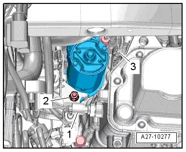
–  Unplug electrical connector -3- from gearbox neutral position sender -G701-.
Continued for all vehicles:
–  Unplug electrical connector -2- at reversing light switch -F4-.
–  Remove nut -1- and detach bracket for electrical wiring. Wiring remains connected.
–  Remove bolt (bottom) and detach starter.
–  Unbolt drive shafts (left and right) from flange shafts on gearbox → Running gear; Rep. gr.40.
  A27-10277
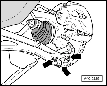
–  Remove nuts -arrows- securing swivel joint (left-side).
–  If fitted, unscrew nut on bracket for front left vehicle level sender -G78-.
–  Disengage swivel joint (left-side) from wishbone.
  A40-0228
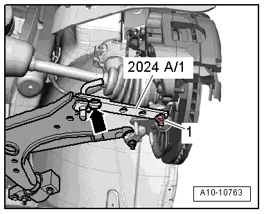
–  Swivel suspension strut (left-side) outwards and support with hook -2024 A /1- as shown in illustration.
  WARNING
Risk of accident if parts of support are not properly secured.
Secure locking pin and swivel joint with retaining clip -arrow- and nut -1-.
–  Tie up drive shafts (left and right).
  Note
Make sure you do not damage surface coating on drive shaft.
–  Remove flange shaft (right-side) → Chapter.
  A10-10763
  WARNING
Risk of accident.
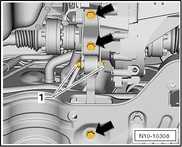
The bolted connection -1- must not be slackened.
–  Remove bolts -arrows- and detach pendulum support.
  N10-10308
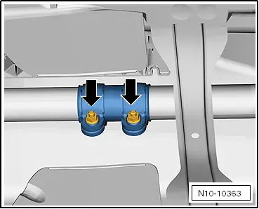
–  Loosen nuts -arrows- and move clamp towards rear.
  N10-10363
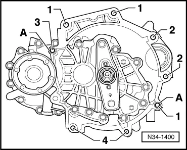
–  Remove bolts -1- (accessible from above).
  N34-1400
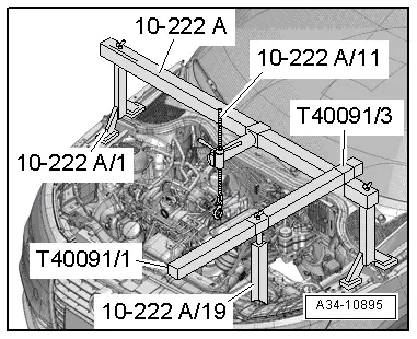
–  Set up support bracket -10 - 222 A- on wing mounting flanges, as shown in illustration.
–  Engage hook of spindle -10 - 222 A /11- in engine lifting eye (left-side).
–  Take up weight of engine with spindle; do not lift.
  A34-10895
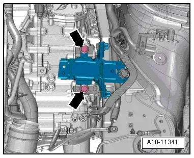
–  Remove bolts -arrows- from gearbox mounting.
  A10-11341
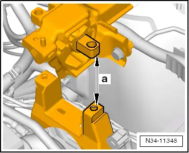
–  Lower engine/gearbox assembly using spindle of support bracket -10 - 222 A- until distance -a- is obtained between gearbox support and gearbox mounting.
l  Dimension -a- = 50 mm
  N34-11348
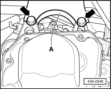
–  Remove bolts -arrows- and detach gearbox support -A-.
  A34-0348
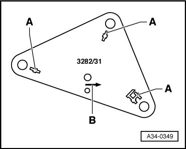
To remove gearbox 02T, set up gearbox support -3282- with adjustment plate -3282/31-.
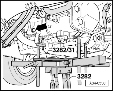
–  Insert gearbox support -3282- in engine and gearbox jack -V.A.G 1383 A-.
–  Align arms of gearbox support according to holes in adjustment plate.
–  Bolt on support elements -A-, as illustrated on adjustment plate.
–  Place engine and gearbox jack -V.A.G 1383 A- underneath vehicle.
l  The arrow symbol -B- on the adjustment plate points in the direction of travel.
  A34-0349
–  Align adjustment plate -3282/31- parallel to gearbox and lock safety support on gearbox.
  Note
-Arrow- can be disregarded.
  A34-0350
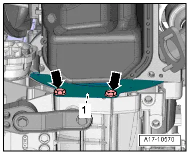
–  Remove bolts -arrows- and detach cover plate -1-.
  A17-10570
–  Remove remaining engine/gearbox securing bolts -1- and -3-.
–  Press gearbox off dowel sleeves.
–  Pull gearbox off engine.
  N34-1400
–  Press engine forward slightly.
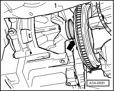
–  Carefully lower gearbox using engine and gearbox jack -V.A.G 1383 A- and ensure sufficient clearance between sleeve -1- and clutch pressure plate -arrow- to prevent damage.
–  While lowering gearbox, change position of gearbox using spindles on gearbox support -3282-.
  A34-0681

Installing gearbox > < Adjusting selector mechanism