
A1
| Exploded view - output shaft |
 Note
Note| t | Refer to → Electronics parts catalogue and technical data when installing new gear wheels or a new output shaft. |
| t | Pressing input and output shaft out of bearing mounting and grooved ball bearings → Chapter |
| t | Lubricate all bearings, selector gears and synchro-rings on output shaft with gear oil before installing. |
| t | Do not interchange synchro-rings. When re-using synchro-rings, always fit on the same selector gear. |
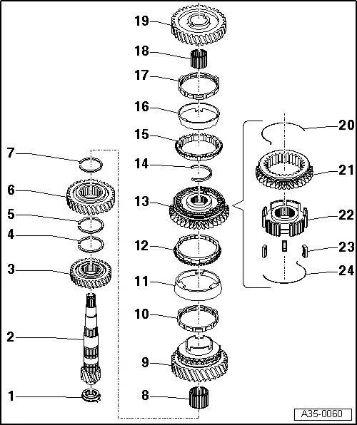
| 1 - | Roller bearing |
| q | With circlip |
| q | Removing and installing → Chapter |
| q | Installation position: the circlip in the bearing faces the output shaft |
| 2 - | Output shaft |
| q | With inner race for roller bearing (depending on version) |
| q | Inner race cannot be removed from output shaft |
| q | Check bearing seat / bearing inner race for scoring or other damage |
| q | If you detect scoring or other damage to the bearing seat / inner race, renew both output shaft and roller bearing |
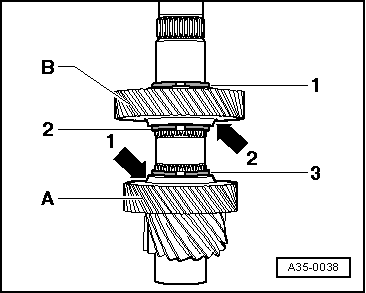
| 3 - | 4th gear wheel |
| q | Installation position: Collar faces 3rd gear → Fig. |
| q | Removing and installing → Chapter |
| 4 - | Circlip |
| 5 - | Circlip |
| 6 - | 3rd gear wheel |
| q | Installation position: Collar faces 4th gear → Fig. |
| q | Removing and installing → Chapter |
| 7 - | Circlip |
| 8 - | Needle bearing |
| q | For 2nd gear |
| 9 - | 2nd speed selector gear |
| 10 - | Inner ring for 2nd gear |
| q | Removing and installing → Chapter |
| q | Checking for wear → |
| 11 - | Outer ring for 2nd gear |
| q | Removing and installing → Chapter |
| q | Renew if scored or if there are visible traces of wear |
| 12 - | 2nd gear synchro-ring |
| q | Removing and installing → Chapter |
| q | Checking for wear → |
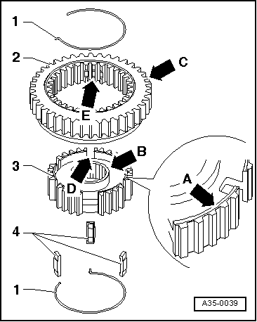
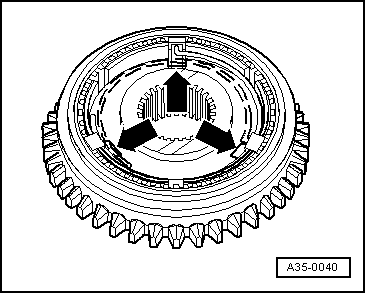
| 13 - | Locking collar with synchronising hub for 1st and 2nd gear |
| q | Removing and installing → Chapter |
| q | Dismantling and assembling → Fig. |
| 14 - | Circlip |
| 15 - | 1st gear synchro-ring |
| q | Removing and installing → Chapter |
| q | Checking for wear → |
| 16 - | Outer ring for 1st gear |
| q | Removing and installing → Chapter |
| q | Renew if scored or if there are visible traces of wear |
| 17 - | Inner ring for 1st gear |
| q | Removing and installing → Chapter |
| q | Checking for wear → |
| q | Check lugs for scoring |
| 18 - | Needle bearing |
| q | For 1st gear |
| 19 - | 1st speed selector gear |
| q | Removing and installing → Chapter |
| 20 - | Spring |
| q | Installation position → Fig. |
| 21 - | Locking collar for 1st and 2nd gear |
| q | Dismantling and assembling → Fig. |
| 22 - | Synchronising hub for 1st and 2nd gear |
| q | Dismantling and assembling → Fig. |
| 23 - | Locking pieces |
| q | 3x |
| 24 - | Spring |
| q | Installation position → Fig. |
|
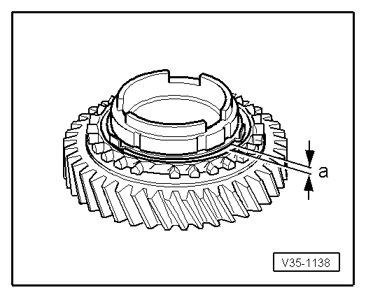
|
| Gap -a- | Installation depth | Wear limit |
| 1st and 2nd gear | 0.75 ... 1.25 mm | 0.3 mm |
|
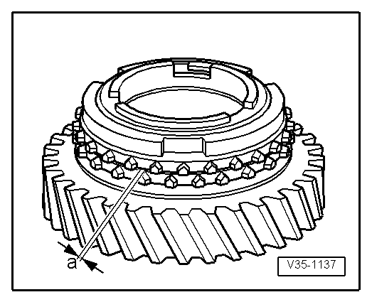
|
| Gap -a- | Installation depth | Wear limit |
| 1st and 2nd gear | 1.2 ... 1.8 mm | 0.5 mm |
|
|
|
|