audi Workshop Repair Guides

Audi Workshop Service and Repair Manuals

Moving mechatronic unit for dual clutch gearboxJ743 into removal position by hand > < Safety notes on mechatronic unit for dual clutch gearboxJ743
Removing and installing mechatronic unit for dual clutch gearboxJ743 with gearbox installed
Removing and installing mechatronic unit for dual clutch gearbox -J743- with gearbox installed
Special tools and workshop equipment required
   
t  Used oil collection and extraction unit -V.A.G 1782-
  W00-10211
t  Engine bung set -VAS 6122-
  W00-10435
t  Guide pin -T10406-
  W00-10784
t  Assembly lever -T10407-
t  Vehicle diagnostic tester
Removing
  Caution
Do not run engine or tow vehicle with mechatronic unit for dual clutch gearbox -J743- removed or when there is no gear oil in the gearbox.
  Note
t  → Chapter „Repair instructions“.
t  → Chapter „Rules for cleanliness when working on the gearbox“.
t  Observe notes on dual clutch gearbox 0AM → Chapter.
t  The clutch is self-adjusting. Shocks can affect the adjusting mechanism. Even if the mechatronic unit has been removed, suddenly pulling out the assembly lever -T10407- from under the engaging levers can have a negative effect on the adjusting mechanism.
t  A new mechatronic unit is supplied with the correct oil filling. Do not drain oil.
t  After removal, the used mechatronic unit is sent back with its oil in. The mechatronic unit remains filled with oil.
  W00-10780
–  Remove radiator cowl → Engine, mechanics; Rep. gr.19.
  Note
t  The vehicle diagnostic tester moves all gear actuators into „neutral“ position.
t  In this position, insert assembly lever -T10407- between engaging lever and gearbox housing. This makes it possible to remove load from the plungers of the mechatronic unit so that they can be removed by hand from the retainers on the engaging levers.
–  Shift selector lever into position „P“.
–  Connect vehicle diagnostic tester and switch on ignition.
–  Select the following menu items:
t  Guided Functions
t  02 - 7-speed dual clutch gearbox
t  Basic setting neutral
–  Switch off ignition.
  A19-11105
  Caution
Risk of irreparable damage to gearbox components.
Never touch the contacts in the gearbox connector with your hands. Electrostatic discharge could cause irreparable damage to the control unit and, consequently, the mechatronic unit.
–  Touch a suitable earthed object with your hand (without gloves) to discharge any static electricity.
–  Release and unplug electrical connector -1- for dual clutch gearbox.
–  Take electrical connector -4- out of bracket.
–  Remove bracket and tie up together with connectors -2- and -3-.
  A10-11343
–  Remove nuts -arrows- and push bracket -1- to one side.
  A34-10688
–  Place used oil collection and extraction unit -V.A.G 1782- below gearbox.
–  Remove oil drain plug -arrow- from gearbox.
  A34-10891
–  Allow oil to drain off, then retighten oil drain plug.
  N34-10931
–  Remove cap from breather opening and seal off with a plug from engine bung set -VAS 6122- to prevent oil from escaping.
  N34-10906
–  Carefully pull gearbox input speed sender -G182- out of gearbox.
  Note
  N34-10907
The following step is necessary in order to lift the two engaging levers of the dual clutch away from the plungers of the mechatronic unit. Otherwise, the levers will jam the mechatronic unit at the plungers and prevent it from being removed.
–  Insert assembly lever -T10407- below plungers -2- between gearbox housing and the two engaging levers -1--arrow-, as shown in illustration.
  A34-10642
–  Only slide in assembly lever -T10407- until groove on assembly lever is in line with rib on housing -arrows-, as shown in illustration. Do not slide it in all the way.
  Note
The back of the assembly lever must make contact with the gearbox housing.
  A34-10643
–  Now rotate assembly lever -T10407- 90° anti-clockwise about its own axis -arrow A- so as to lift engaging levers away from plungers -1--arrow B-.
  A34-10644
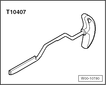
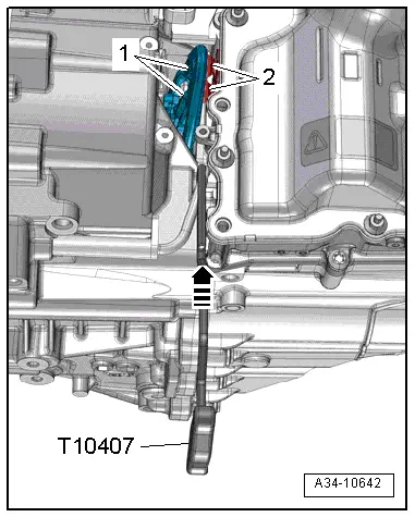
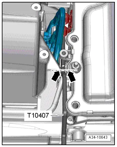
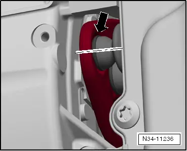
–  If necessary, press the assembly lever -T10407- against the gearbox housing with a screwdriver to prevent it from slipping out when it is turned.
  Note
t  
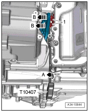
The assembly lever -T10407- remains inserted between the engaging levers and the gearbox housing while removing and installing the mechatronic unit.
t  If necessary, press the assembly lever -T10407- against the gearbox housing.
  Caution
Risk of irreparable damage to gearbox components.
t  Before touching or removing the mechatronic unit for dual clutch gearbox -J743-, always discharge any static electricity by touching an earthed object with your hand.
t  Never touch the contacts in the gearbox connector with your hands. Electrostatic discharge could cause irreparable damage to the control unit and, consequently, the mechatronic unit.
–  Touch a suitable earthed object with your hand (without gloves) to discharge any static electricity.
  Note
Make sure that the screwdriver used to support the assembly lever -T10407- does not jam against the mechatronic unit.
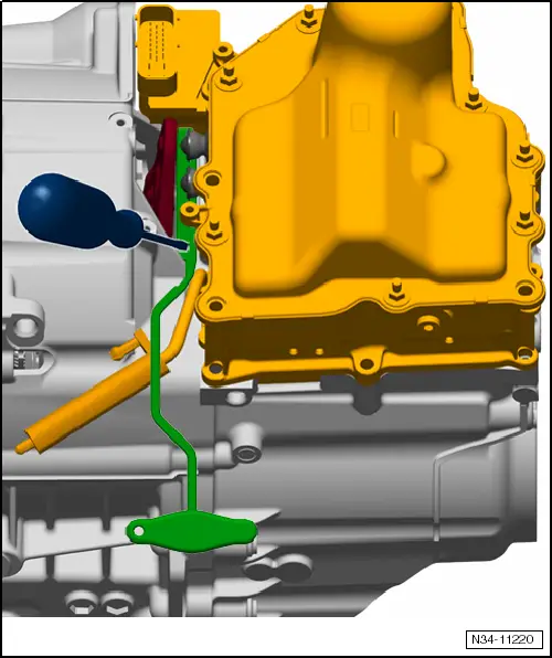
  Caution
Risk of damage to mechatronic unit for dual clutch gearbox -J743-!
t  
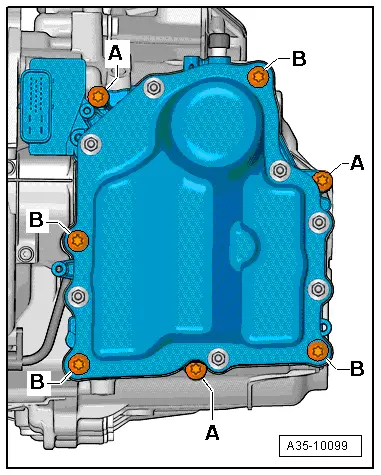
Do not loosen bolts securing cover on mechatronic unit for dual clutch gearbox -J743-.
t  Make sure that no oil escapes through the breather hole when placing down mechatronic unit for dual clutch gearbox -J743- after removal.
t  Oil that has escaped cannot be refilled!
  Note
The mechatronic unit is returned for reconditioning complete with oil filling.
  N34-11220
–  Remove bolts -B- in diagonal sequence.
–  Remove bolts -A-.
–  Detach mechatronic unit from gearbox.
  Caution
Risk of damage to mechatronic unit for dual clutch gearbox -J743-.
t  In some cases it may not be possible to remove the mechatronic unit.
t  This can happen if the gear actuator at the top left of the mechatronic unit is stuck.
t  Do not attempt to remove the mechatronic unit by force.
t  The mechatronic unit must be first brought into the correct position for removal by hand → Chapter.
Installing
l  Tightening torques → Fig. „„Mechatronic unit for dual clutch gearbox -J743-: tightening torque and sequence““
  Note
A new mechatronic unit is supplied with the correct oil filling.
  A35-10099
–  Seal off breather opening of mechatronic unit with a cap from engine bung set -VAS 6122- to prevent oil from escaping.
  N34-10906
  Note
t  Make sure that all selector forks are in „centre position“ before installing mechatronic unit for dual clutch gearbox -J743-.
t  „Centre position“ is position -N- (neutral) in the illustration below.
t  No gear is engaged in this position, the gearbox is in neutral.
N - Neutral
R - Reverse gear
1 - First gear
2 - Second gear
3 - Third gear
4 - Fourth gear
5 - Fifth gear
6 - Sixth gear
7 - Seventh gear
–  First check each of the 4 selector forks by hand.
Each selector fork has 3 positions:
t  Gear engaged
t  Neutral -N-
t  Gear engaged
–  Move the 4 selector forks once into each position -arrows-, one after the other.
–  Then shift all selector forks back into »centre position«, position -N-.
  Note
Turn one of the wheels slightly to make it easier to move the selector forks.

   
–  Clean sealing surface on which mechatronic unit is to be installed.
–  Screw in bolt guide pins -T10406- hand-tight.
  N34-11361
Adjusting gear actuators:
  Caution
Risk of damage to mechatronic unit for dual clutch gearbox -J743-.
Do not apply any pressure to the sensors when levering out the plungers.
–  Adjust the four gear actuators on the reverse side of mechatronic unit for dual clutch gearbox -J743- to the specified positions.
l  Specified position: -a- = 25 mm

–  Clean sealing surface on mechatronic unit.
l  The gasket positioned round the mechatronic unit for dual clutch gearbox -J743- must be properly seated in the groove all round.
   
–  Put on mechatronic unit.
–  Tighten bolts for mechatronic unit → Fig..
  Caution
The clutches can be damaged.
If the clutch engaging levers contact the clutch actuators of the mechatronic unit abruptly, this can move the actuators out of position and activate the clutch self-adjustment. The status prior to self-adjustment cannot be recovered.
l  Both clutch actuators must be properly engaged in the retainers on the clutch engaging levers.
l  The rubber grommets of the clutch actuators must not be damaged.
l  The rubber grommets must seal off at the mechatronic unit properly.
  A35-10099
–  Turn assembly lever -T10407- slowly and carefully in clockwise direction and remove.
l  The plungers should slide slowly into the retainers.
–  Pull out plungers by hand until they are seated correctly in retainers.
  N34-11236
–  Install gearbox input speed sender -G182- in opposite direction of -arrow-.
  N34-10907
–  Fit cover.
  N34-10896
–  Remove sealing plug from breather opening of mechatronic unit and fit breather cap -arrow-.
  Note
t  If the mechatronic unit is being renewed, fit the sealing plug on the old mechatronic unit so it remains oil-tight when it is returned for reconditioning.
t  Do not drain oil out of the old mechatronic unit.
  N34-10906
  Caution
Risk of damage to gearbox components.
Never touch the contacts in the gearbox connector with your hands. Electrostatic discharge could cause irreparable damage to the control unit and, consequently, the mechatronic unit.
–  Touch a suitable earthed object with your hand (without gloves) to discharge any static electricity.
–  Attach electrical connector -1- for dual clutch gearbox and lock.
–  Install bracket with electrical connectors -2, 3 and 4-.
Remaining assembly is carried out in reverse sequence; note the following:
–  Install radiator cowl → Engine, mechanics; Rep. gr.19.
–  Fill up gear oil → Chapter.
–  Observe measures which have to be taken after connecting the battery → Electrical system; Rep. gr.27.
–  Check adjustment of selector lever cable and adjust if necessary → Chapter.
–  After installing the gearbox, run the Basic setting complete function in Guided Functions → Vehicle diagnostic tester.
  A10-11343

Moving mechatronic unit for dual clutch gearboxJ743 into removal position by hand > < Safety notes on mechatronic unit for dual clutch gearboxJ743