audi Workshop Repair Guides

Audi Workshop Service and Repair Manuals

Valve gear > < Removing and installing cylinder head
Checking compression
Special tools and workshop equipment required
   
t  Spark plug socket and extension -3122 B-
  W00-0060
t  Compression tester -V.A.G 1763-
  W00-0563
t  Puller -T10094 A-
Procedure
l  Engine oil temperature min. 30 °C.
l  Battery voltage at least 12.5 V.
–  Switch off ignition.
–  Remove fuse for fuel pump control unit -J538- from fuse holder C in fuse carrier 2 on right side of dash panel; for fuse assignment see → Current flow diagrams, Electrical fault finding and Fitting locations.
  W00-10526
–  Pull off engine cover panel (front) -arrows- and remove towards front.
  A10-11413
–  Remove bolts -1 and 3-.
–  Release hose clip -2-, detach air pipe (top right) and remove air hose.
  A21-10567
–  Unplug electrical connector -2-.
–  Detach vacuum hoses -1-.
  A21-10570
–  Unplug electrical connector -4-.
–  Remove bolts -1 and 3-.
–  Press release tabs and disconnect crankcase breather hoses -arrows-.
–  Release hose clip -2- and disconnect hose at activated charcoal filter.
–  Detach hoses.
  A10-11415
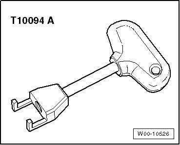
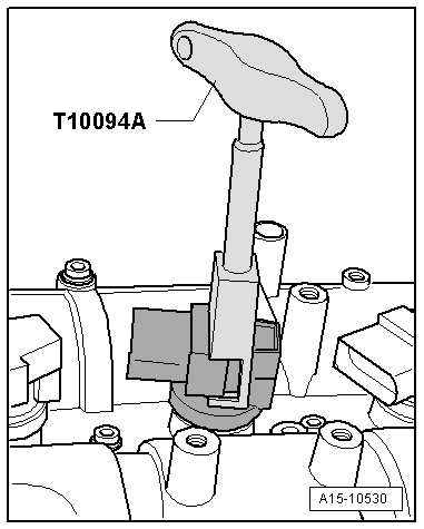
–  Apply puller -T10094 A- to all ignition coils, pull out ignition coils and at the same time unplug electrical connectors at ignition coils for cylinders 1 ... 4.
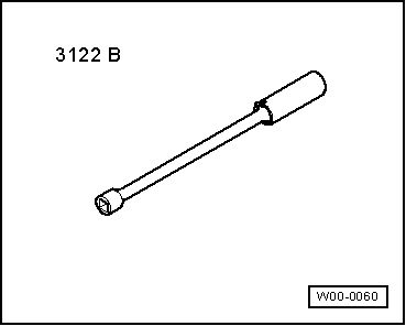
–  Remove spark plugs with spark plug socket and extension -3122 B-.
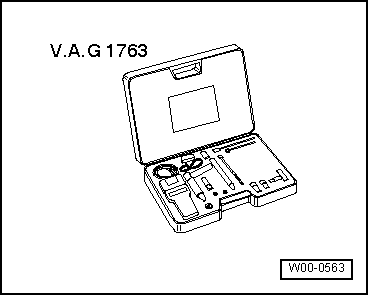
–  Check compression pressure with compression tester -V.A.G 1763- (see → operating instructions for details of how to use tester).
–  Have a 2nd mechanic press down the accelerator pedal completely and at the same time operate the starter until the pressure on the tester display no longer increases.
–  Repeat procedure on each cylinder.
  A15-10530
Compression pressurebar
When new10.0 … 15.0
Wear limit9.0
Maximum difference between cylinders3.0

Installation is carried out in the reverse order; note the following:
–  Install spark plugs → Booklet819.
–  Install air pipe (top right) → Chapter.
–  Install air hoses with screw-type clips → Fig..
–  Faults are stored in the engine control unit because the fuse for the Motronic current supply relay -J271- was removed and the engine was started: Generate readiness code in Guided Functions using → Vehicle diagnostic tester.
   

Valve gear > < Removing and installing cylinder head