
A1
| Cylinder head - exploded view |

| 1 - | Cylinder head |
| q | Removing and installing → Chapter |
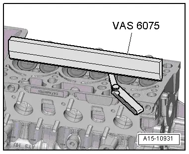
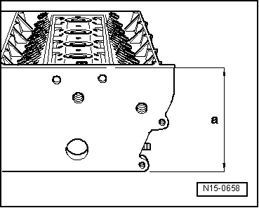
| q | Checking for distortion → Fig. |
| q | Sealing surface for camshaft housing must be free of oil and grease |
| q | If renewed, change coolant and engine oil |
| 2 - | Guide pin |
| q | Tightening torque → Item |
| 3 - | Bolt |
| q | 20 Nm |
| 4 - | Engine lifting eye |
| 5 - | Hydraulic valve compensation element |
| q | Do not interchange |
| q | Lubricate running surfaces with oil |
| 6 - | Securing clip |
| q | Check for firm attachment |
| q | Not supplied separately |
| 7 - | Roller rocker finger |
| q | Check roller bearings for ease of movement |
| q | Lubricate contact surfaces before installing |
| q | Attach to hydraulic compensation element -item 5- using securing clip -item 6- |
| 8 - | Oil strainer |
| q | Inserted into cylinder head |
| q | Renew |
| 9 - | Seal |
| q | Inserted into cylinder head |
| q | 4x |
| q | Renew |
| 10 - | Camshaft housing |
| q | Removing and installing → Chapter |
| 11 - | Bolt |
| q | Renew |
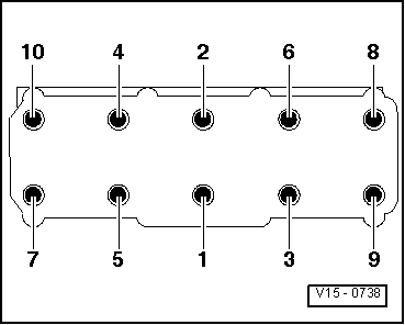
| q | Note correct sequence when loosening → Anchor |
| q | Tightening torque and sequence → Fig. |
| 12 - | Bolt |
| q | 20 Nm |
| 13 - | Engine lifting eye |
| 14 - | Bolt |
| q | Renew |
| q | Note correct sequence when loosening → Anchor |
| q | Tightening torque and sequence → Fig. |
| 15 - | Cylinder head gasket |
| q | Renewing → Chapter „Removing and installing cylinder head“ |
| q | Installation position: Part number points towards cylinder head, and must be legible from the inlet side |
| q | If renewed, change coolant and engine oil |
|
|
|
|
 Note
Note
|
|
| Stage | Bolts | Tightening torque/angle specification |
| 1. | -1 … 10- | Screw in bolts by hand until they make contact |
| 2. | -1 … 10- | 20 Nm |
| 3. | -1 … 10- | turn 90° further |
| 4. | -1 … 10- | turn 90° further |