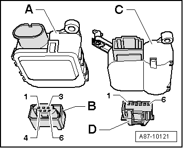
A2
|

|
Vehicle diagnostic, testing and information system -VAS 5051-, measurement mode: Multimeter, resistance measurement (20 kΩ)
| |||||||||||||||||
| Test step | Test box -V.A.G 1598 A- socket | Being tested: (the wiring to the) |
| Specification | Remedies if the specification is not attained | ||||||||||||
| 4.1 | 25 and 36 | Potentiometer - positioning motor for temperature flap -G92- (in the positioning motor for temperature flap -V68-) |
|
|
| ||||||||||||
| 25 and 38 | Potentiometer - positioning motor for central flap -G112- (in the positioning motor for central flap -V70-) | ||||||||||||||||
| 25 and 39 | Potentiometer in positioning motor for recirculated-air flap -G143- (in the positioning motor for recirculated-air flap -V113-) | ||||||||||||||||
| 25 and 37 | Potentiometer in positioning motor for defrost flap -G135- (in the positioning motor for defrost flap -V107-) | ||||||||||||||||
Vehicle diagnostic, testing and information system -VAS 5051-, measurement mode: Multimeter, resistance measurement (20 kΩ)
| |||||||||||||||||
| Test step | Test box -V.A.G 1598 A- socket | Being tested: (the wiring to the) |
| Specification | Remedies if the specification is not attained | ||||||||||||
| 4.2 | 34 and 36 | Potentiometer - positioning motor for temperature flap -G92- (in the positioning motor for temperature flap -V68-) |
|
|
| ||||||||||||
| 34 and 38 | Potentiometer - positioning motor for central flap -G112- (in the positioning motor for central flap -V70-) | ||||||||||||||||
| 34 and 39 | Potentiometer in positioning motor for recirculated-air flap -G143- (in the positioning motor for recirculated-air flap -V113-) | ||||||||||||||||
| 34 and 37 | Potentiometer in positioning motor for defrost flap -G135- (in the positioning motor for defrost flap -V107-) | ||||||||||||||||
Vehicle diagnostic, testing and information system -VAS 5051-, measurement mode: Multimeter, resistance measurement (20 kΩ)
| |||||||||||||||
| Test step | Test box -V.A.G 1598 A- socket | Being tested: (the wiring to the) |
| Specification | Remedies if the specification is not attained | ||||||||||
| 4.3 | Earth → Note and 36 | Potentiometer - positioning motor for temperature flap -G92- (in the positioning motor for temperature flap -V68-) |
|
|
| ||||||||||
| Earth → Note and 38 | Potentiometer - positioning motor for central flap -G112- (in the positioning motor for central flap -V70-) | ||||||||||||||
| Earth → Note and 39 | Potentiometer in positioning motor for recirculated-air flap -G143- (in the positioning motor for recirculated-air flap -V113-) | ||||||||||||||
| Earth → Note and 37 | Potentiometer in positioning motor for defrost flap -G135- (in the positioning motor for defrost flap -V107-) | ||||||||||||||
|
Vehicle diagnostic, testing and information system -VAS 5051-, measurement mode: Multimeter, resistance measurement (200 Ω)
| |||||||||||||||
| Test step | Test box -V.A.G 1598 A- socket | Being tested: (the wiring to the) |
| Specification | Remedies if the specification is not attained | ||||||||||
| 4.4 | 21 + 22 | Temperature flap positioning motor -V68- |
|
|
| ||||||||||
| 4.5 | 26 + 27 | Central flap positioning motor -V70- |
| ||||||||||||
| 4.6 | 28 + 29 | Recirculated-air flap positioning motor -V113- | |||||||||||||
| 4.7 | 23 + 24 | Defrost flap positioning motor -V107- | |||||||||||||
Vehicle diagnostic, testing and information system -VAS 5051-, measurement mode: Multimeter, resistance measurement (200 Ω)
| |||||||||||||||
| Test step | Test box -V.A.G 1598 A- socket | Being tested: (the wiring to the relevant positioning motor for a short circuit to earth) |
| Specification | Remedies if the specification is not attained | ||||||||||
| 4.8 | Earth → Note and 21 | Temperature flap positioning motor -V68- |
|
|
| ||||||||||
| Earth → Note and 23 | Defrost flap positioning motor -V107- | ||||||||||||||
| Earth → Note and 26 | Central flap positioning motor -V70- | ||||||||||||||
| Earth → Note and 28 | Recirculated-air flap positioning motor -V113- | ||||||||||||||
|
Vehicle diagnostic, testing and information system -VAS 5051-, measurement mode: Multimeter, voltage measurement (20 V =)
| |||||||||||||||
| Test step | Test box -V.A.G 1598 A- socket | Being tested: (the wiring to the relevant positioning motor for a short circuit to positive) |
| Specification | Remedies if the specification is not attained | ||||||||||
| 4.9 | Earth → Note and 21 | Temperature flap positioning motor -V68- |
|
|
| ||||||||||
| Earth → Note and 23 | Defrost flap positioning motor -V107- | ||||||||||||||
| Earth → Note and 26 | Central flap positioning motor -V70- | ||||||||||||||
| Earth → Note and 28 | Recirculated-air flap positioning motor -V113- | ||||||||||||||
|

 Note
Note