| The oscilloscope screen displays the following, depending on the setting on the operating and display unit for air conditioner/Climatronic -E87-: |
| –
| In “OFF” or “Econ” mode: No square-wave signal (the air conditioner compressor regulating valve -N280- is not actuated). |
| –
| In “Auto” mode and at “Lo” temperature setting: there is a square-wave signal with a pulse width between 75% and 100% (theair conditioner compressor regulating valve -N280- is actuated). |

Note | t
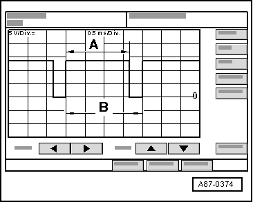
| The illustration shows a signal with a signal ratio of approx. 80 % . |
| t
| The pulse width -A- is governed by the required refrigeration capacity, the vehicle system voltage etc. (over the width of area -A-, current is controlled via the air conditioner compressor regulating valve -N280- by the operating and display unit for air conditioner/Climatronic -E87-). |
| t
| The signal interval -B- is always 2 milliseconds (corresponding to a frequency of 500 Hertz). |
| t
| The signal ratio is derived from the ratio of pulse width -A- to signal interval -B-. |
| –
| The setting on the operating and display unit for air conditioner/Climatronic -E87- and the measured ambient influences govern the pulse width of the square-wave signal (a signal ratio between 100 % and greater than 30 %, the air conditioner compressor regulating valve -N280- is actuated such that compressor output required to obtain the specified temperatures is achieved). |
Note | t
| In “Auto” mode with a “Lo” temperature setting, the air conditioner compressor regulating valve -N280- is actuated such that the max. permissible current of approx. 0.65 A to 0.8 A flows via air conditioner compressor regulating valve -N280- (maximum compressor output). |
| t
| In control mode, the actuation time is governed by the required refrigeration capacity, the vehicle system voltage, etc. However, it always lasts long enough to achieve a mean current of 0.3 A. |
|
|
|

