audi Workshop Repair Guides

Audi Workshop Service and Repair Manuals

Adjusting selector mechanism > < Exploded view - removing and installing selector cables
Removing and installing selector mechanism
Special tools and workshop equipment required
t  Polycarbamide grease -G 052 142 A2-
t  Silicone grease -G 000 405 A2-
Removing
–  First check whether a coded radio is fitted. If this is the case obtain the anti-theft coding.
–  With the ignition switched off, disconnect battery earth strap.
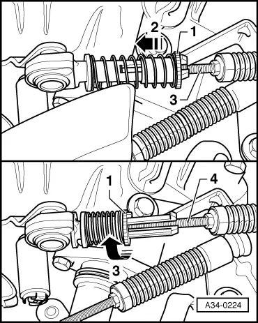
Release cable end-pieces for gate selector cable and gear selector cable as follows:
   
–  Press locking sleeve -1- in direction of -arrow 2- up to stop.
–  Turn locking sleeve -1- as far as it will go in direction of -arrow 3- and allow it to engage.
  Note
t  It should be possible to move selector cable -4- in the cable end-piece.
t  The illustration shows the gate selector cable. The gear selector cable is released in the same way.
–  Pull gear selector cable and gate selector cable out of cable end-pieces.
  A34-0224
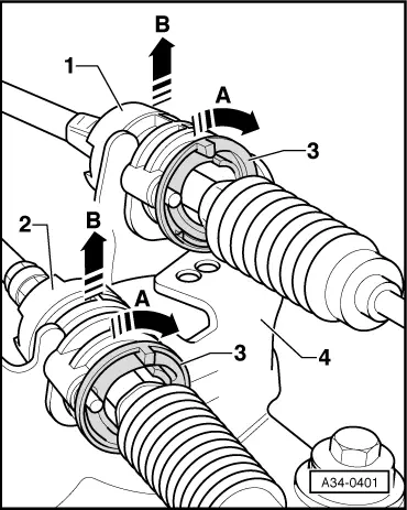
Remove gear selector cable -1- and gate selector cable -2- from cable support bracket -4- as follows:
–  Turn release ring -3- in direction of -arrow A- as far as stop and pull cable out of cable support bracket -4- in direction of -arrow B-.
–  Move both cables clear towards rear.
  A34-0401
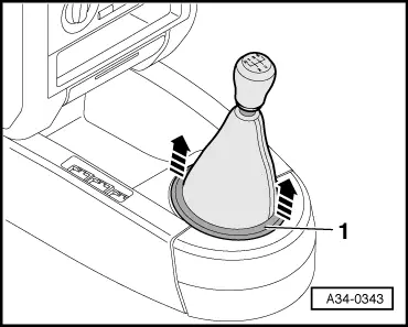
–  Lift gear lever boot -1- off centre console in direction of -arrow-.
–  Pull boot up and over gear knob.
  A34-0343
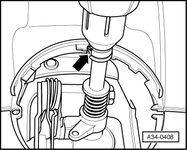
–  Open clip -arrow- and pull off gear knob together with boot.
–  Remove centre console (rear) → Rep. Gr.68.
  A34-0408
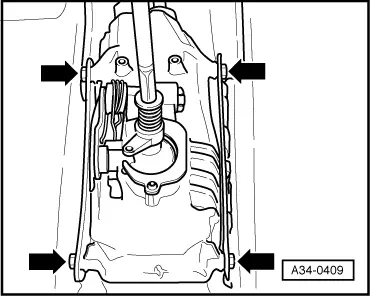
–  Remove securing bolts -arrows- for selector housing.
  A34-0409
–  Pull off both securing clips -1- and securing clips -2-.
–  Use screwdriver to pry off selector cable -arrow- and pull off selector housing from cables.
–  Raise vehicle.
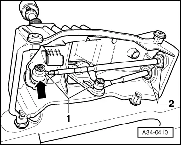
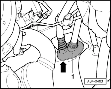
  A34-0410
–  Pry out rubber boot -1- from below using a screwdriver -arrow-.
–  Pull out both cables downwards.
Installing
Assembly is carried out in the reverse order to removal; note the following:
  Note
A second mechanic is required inside the vehicle to assist when installing the cables.
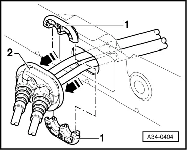
  A34-0403
–  Renew both clamping pieces -1-; they will be damaged upon removal.
–  Fit clamping pieces -1- together and press into rubber boot -2-.
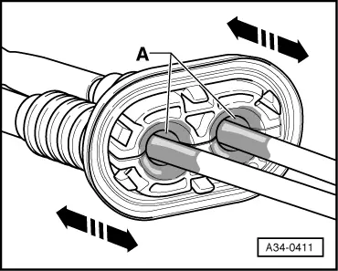
  Note
Make sure that sufficient silicon grease -G 000 405 A2- is applied in area -A- to clamping pieces and cables.
  A34-0404
–  Push rubber boot several times back and forth in direction of -arrow-, to make sure silicon grease -G 000 405 A2- is applied to cables and clamping pieces.
   -A-Silicone grease -G 000 405 A2-
  A34-0411
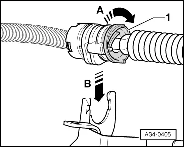
–  Turn release ring -1- in direction of -arrow A- as far as stop and guide cable into cable support bracket in direction of arrow -B-.
–  Let go of release ring -1- again and make sure that both cables are locked in cable support bracket.
  Note
In addition, the gear selector cable must be clipped into the cable retainer (located on the support bracket).
–  Install selector housing and tighten to 9 Nm.
–  Install centre console → Rep. Gr.68.
Adjust selector mechanism → Chapter.
  A34-0405

Adjusting selector mechanism > < Exploded view - removing and installing selector cables