audi Workshop Repair Guides

Audi A2 Workshop Service and Repair Manuals

Checking gearbox oil > < Adjusting selector mechanism
Removing and installing gearbox
   
Removing and installing gearbox
Special tools and workshop equipment required
t  Support bracket -10 - 222 A- with adapters -10 - 222 A /13-
t  Shackle -10 - 222 A /12-
t  Gearbox support -3282-
t  Adjustment plate -3282/31-
t  Gearbox lifting tackle -3336-

   
t  Engine and gearbox jack -V.A.G 1383 A-
  W00-0120
t  Tensioning strap -T10038-
t  Grease for clutch plate splines -G 000 100-
Removing
–  Remove bonnet → Rep. Gr.55.
–  First check whether a coded radio is fitted. If this is the case obtain the anti-theft coding.
–  With the ignition switched off, disconnect battery earth strap.
–  Pull off rubber seal at plenum chamber.
–  Detach wiper arm and scuttle panel trim.
  W00-1005
–  Remove both bolts -A- and three hexagon nuts -B-.
–  Detach the fresh air intake duct towards the front.
  A80-0202
–  Pull locking mechanism on gear selector cable and gate selector cable forwards -arrow 1- onto stop and then turn to left -arrow 2- to lock.
–  Pull securing clip -arrow 3- off relay lever -A- and remove relay lever.
–  Remove gearbox selector lever -B- by removing nut -arrow 4-.
  A34-0323
–  Pull pipe/hose assembly -A- out of bracket on gearbox.
–  Remove clutch slave cylinder -B-, place to one side and secure with wire. Do not disconnect pipes.
  Note
Do not depress clutch pedal.
  A34-0324
–  Unscrew two bolts securing cable support bracket from gearbox -arrows-.
  Note
The third bolt for the cable support bracket is removed from the gearbox from below, with the vehicle raised ⇒ → Anchor.
–  Detach earth strap at upper engine/gearbox connecting bolt.
–  Then remove upper securing bolt from starter.
  A34-0324
–  Assemble support bracket -10 - 222 A- together with adapters -10 - 222 A /13- and shackle -10 - 222 A /12-.
  Note
Engage the adapters -10 - 222 A /13- at the rear in the mounting hooks for the bonnet -arrow-.
–  Partly take up weight of engine/gearbox assembly via the spindle.
–  Loosen bolts for left front wheel.
–  Raise vehicle.
–  Remove left wheel.
–  Remove noise insulation.
  A34-0325
–  Remove connector -arrow 1- from starter.
–  Unplug connector from reversing light switch -F4--arrow 2-.
–  Remove bracket -A- on starter -arrow 3-.
–  Unscrew wire -arrow 4- from solenoid switch terminal 30.
–  Remove starter → Rep. Gr.27.
  A34-0326
–  Remove heat shield -1- from pendulum support -2-.
–  Remove pendulum support -arrows A and B-.
–  Unbolt drive shafts from gearbox flange shafts.
–  Lift drive shaft (right-side) up and secure.
  A34-0327
–  If fitted, unplug connector from speedometer sender -G22--arrow-.
–  Remove third bolt -A- for cable support bracket from gearbox.
–  Tie back gear selector cable and gate selector cable.
–  Remove engine/gearbox securing bolt -B- above flange shaft (right-side).
  A34-0345
–  Release coupling rod (left-side) -1- from anti-roll bar.
–  Detach suspension link (left-side) from wheel bearing housing -arrow- → Rep. Gr.40.
–  Remove wheel housing liner from wheel housing (left-side).
–  Swivel wheel bearing housing outwards.
–  Guide drive shaft (left-side) out between subframe and gearbox.
–  Guide drive shaft into the wheel housing and secure to suspension strut e.g. with wire or similar.
  A39-0328
–  Unclip wiring -1- for lambda probe from heat shield -arrow A-.
–  Remove bracket for exhaust system from underbody -arrows B-.
–  Separate exhaust system at double clamp -2-.
–  Secure exhaust system to heat shield using tensioning strap -T10038-.
  A34-0346
–  Remove hexagon bolts -arrows- at left mounting from gearbox mounting.
–  Tilt engine/gearbox assembly; for this purpose, lower via spindle of support bracket -10 - 222 A-.
  Note
When lowering the engine/gearbox assembly, make sure that the gearbox does not contact the subframe in the vicinity of the differential.
l  Bolts -arrows- securing gearbox bracket -A- must be accessible.
  A34-0347
–  Detach gearbox bracket -A--arrows-.
–  Set up gearbox jack with gearbox support -3282-, adjustment plate -3282/31- for gearbox “02T” and supporting elements as follows:
–  Place adjustment plate -3282/31- on gearbox support -3282-. (Adjustment plate can only be fitted in one position.)
–  Align arms of gearbox support according to holes in adjustment plate.
  A34-0348
–  Bolt on support elements -A-, as illustrated on adjustment plate.
  A34-0349
–  Place engine and gearbox jack under vehicle; arrow symbol -B- ( → Anchor) on adjustment plate points to front of vehicle.
–  Align adjustment plate parallel to gearbox and lock safety support on gearbox.
–  Remove bottom engine/gearbox connecting bolts.
–  Remove engine/gearbox connecting bolt -arrow-.
–  Push the gearbox off the dowel sleeves and swing carefully towards the subframe.
–  Carefully push engine towards front (2nd mechanic required).
–  Turn gearbox downwards in vicinity of differential.
  A34-0350
–  Then lower gearbox carefully, guiding right-hand flange shaft -A- past flywheel as illustrated and left-hand flange shaft -B- past subframe.
–  When lowering the gearbox, change position of gearbox using the spindles on gearbox support -3282-.
Transporting gearbox
  A34-0351
–  Bolt gearbox lifting tackle -3336- to clutch housing.
  A34-0320
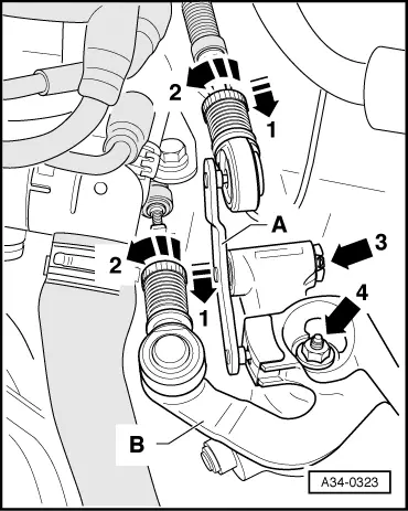
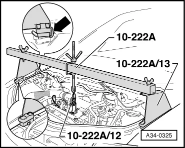
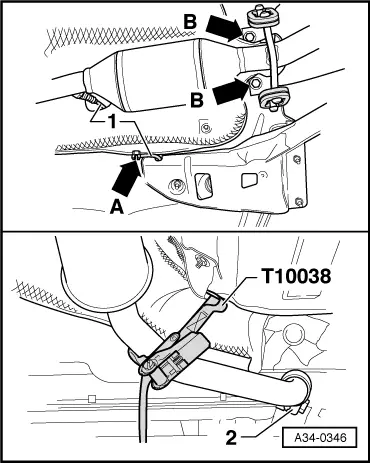
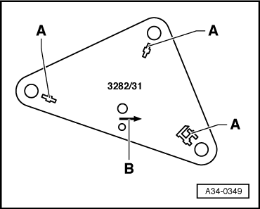
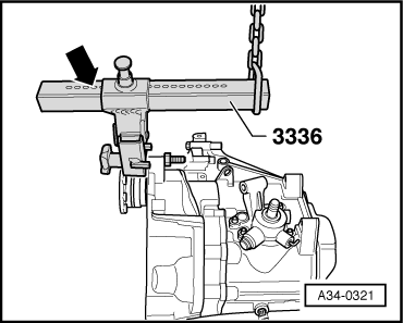
–  Set support arm on sliding bracket by means of locking pin -arrow-.
Number of holes visible = 5
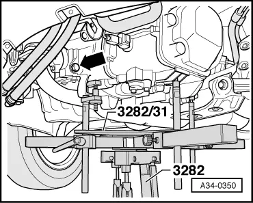
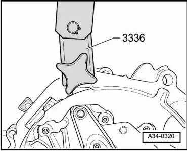
–  Take up gearbox with workshop hoist and gearbox lifting tackle -3336-.
–  Set down gearbox as required (for example in transport container).
Installing
Installation of gearbox is carried out in reverse order of removal. When installing gearbox, ensure that engine/gearbox mountings are free of stress → Rep. Gr.10.
  Note
t  Clean splines of input shaft and apply a thin coat of grease for clutch plate splines -G 000 100-.
t  When renewing gearbox, ensure that intermediate plate is correctly positioned.
t  Check that dowel sleeves for centralising engine/gearbox are in the cylinder block, install if necessary.
t  Check gearbox oil → Chapter.
t  Installing starter/wiring → Rep. Gr.27.
t  
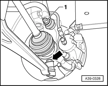
Secure coupling rod to anti-roll bar and suspension link to wheel bearing housing → Rep. Gr.40.
t  Adjusting selector mechanism → Chapter.
t  When the battery is reconnected, please remember to check and activate the vehicle equipment (radio, clock, convenience electrical systems etc.).
Tightening torques
  A34-0321
Gearbox to engine
  A34-0319
ItemBoltQty.Nm
1 1)M 12 x 65180
2 2)M 12 x 140280
3M 12 x 80180
4M 10 x 50245
5M 12 x 65180
ADowel sleeves for centralising
l  1) Bolt with stud M8
l  2) Also starter to gearbox

   
Gearbox bracket -A- to gearbox
–  Renew bolts.
  A34-0348
Bolts -arrows-50 Nm and then turn 90° further

   
Gearbox to body
–  Renew bolts.
  A34-0347
Bolts -arrows-40 Nm and then turn 90° further

   
Rear gearbox mounting
–  Renew bolts.
  A34-0327
Bolt -A-40 Nm and then turn 90° further
Bolts -B-50 Nm

   
Drive shaft to flange shaft → Rep. Gr.40
Selector cable support bracket to gearbox20 Nm
Gearbox selector lever to gearbox20 Nm 1)
Clutch slave cylinder to gearbox23 Nm
Double clamp to exhaust pipe40 Nm
Protective plate to pendulum support23 Nm
Wheel bolts to wheel hub → Rep. Gr.44
l  1) Renew nut


Checking gearbox oil > < Adjusting selector mechanism