audi Workshop Repair Guides

Audi Workshop Service and Repair Manuals

Adjusting selector mechanism > < Removing and installing selector cables - exploded view
Removing and installing selector mechanism
Special tools and workshop equipment required
t  Polycarbamide grease -G 052 142 A2-
t  Silicone grease -G 000 405 A2-
Removing
–  First check whether a coded radio is fitted. If this is the case obtain the anti-theft coding.
–  With the ignition switched off, disconnect battery earth strap.
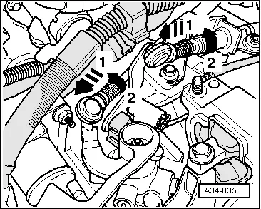
Release cable end-pieces for gate selector cable and gear selector cable as follows:
   
–  Pull locking mechanism on gate selector cable and gear selector cable forwards in direction of -arrow 1- onto stop.
–  Turn locking sleeve in direction of -arrow 2- up to limit stop and clip locking sleeve in place.
  Note
It should now be possible to move the cable in the cable end-piece.
–  Pull gear selector cable and gate selector cable out of cable end-pieces.
  A34-0353
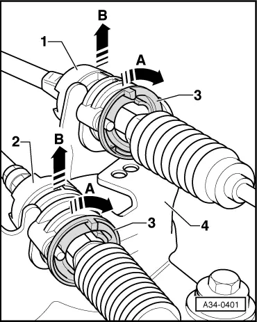
Remove gear selector cable -1- and gate selector cable -2- from support bracket -4- as follows:
–  Turn release ring -3- in direction of -arrow A- as far as stop and pull cable out of support bracket -4- in direction of -arrow B-.
–  Move both cables clear towards rear.
  A34-0401
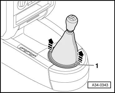
–  Lift gear lever boot -1- off centre console in direction of -arrow-.
–  Pull boot up and over gear knob.
  A34-0343
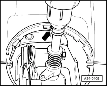
–  Open clip -arrow- and pull off gear knob together with boot.
–  Remove centre console (rear) → Rep. Gr.68.
  A34-0408
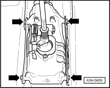
–  Remove securing bolts -arrows- for selector housing.
  A34-0409
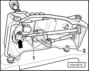
–  Pull off both securing clips -1- and securing clips -2-.
–  Use screwdriver to pry off selector cable -arrow- and pull off selector housing from cables.
–  Raise vehicle.
  A34-0410
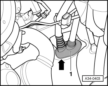
–  Pry out rubber boot -1- from below using a screwdriver -arrow-.
–  Pull out both cables downwards.
Installing
Assembly is carried out in the reverse order to removal; note the following:
  Note
A second mechanic is required in passenger compartment to assist insertion of cables.
  A34-0403
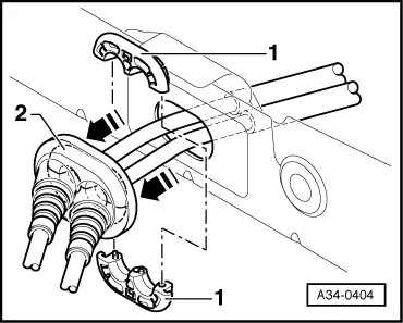
–  Renew both clamping pieces -1-; they will be damaged upon removal.
–  Fit clamping pieces -1- together and press into rubber boot -2-.
  Note
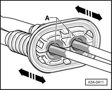
Make sure that sufficient silicon grease -G 000 405 A2- is applied in area -A- to clamping pieces and cables.
  A34-0404
–  Push rubber boot several times back and forth in direction of -arrow-, to make sure silicon grease -G 000 405 A2- is applied to cables and clamping pieces.
-A-Silicone grease -G 000 405 A2-
  A34-0411
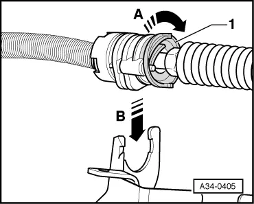
–  Turn release ring -1- in direction of -arrow A- as far as stop and guide cable into support bracket in direction of arrow -B-.
–  Let go of release ring -1- again and make sure that both cables are locked in support bracket.
  Note
In addition, the gear selector cable must be clipped into cable bracket (located at support bracket).
–  Install selector housing and tighten to 9 Nm.
–  Install centre console → Rep. Gr.68.
Adjusting selector mechanism → Chapter.
  A34-0405

Adjusting selector mechanism > < Removing and installing selector cables - exploded view