
A2
| Dismantling and assembling input shaft |

| Special tools and workshop equipment required |
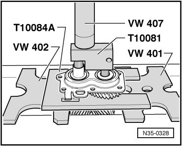
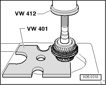
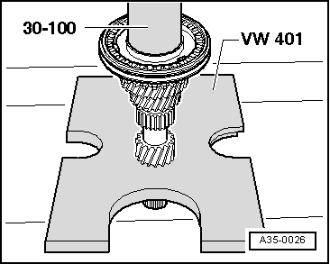
| t | Thrust plate -VW 401- |
| t | Thrust plate -VW 402- |
| t | Press tool -VW 407- |
| t | Press tool -VW 412- |
| t | Tube -VW 415 A- |
| t | Tube -VW 422- |
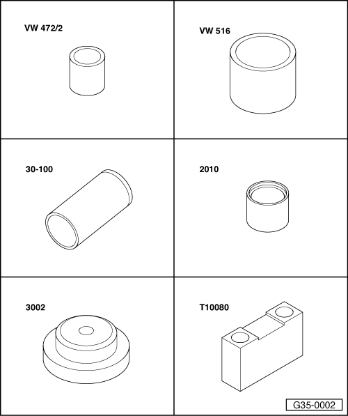
| t | Spacer sleeve -VW 472/2- |
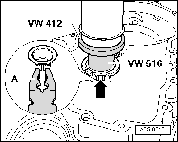
| t | Tube -VW 516- |
| t | Drift sleeve -30 - 100- |
| t | Tube -2010- |
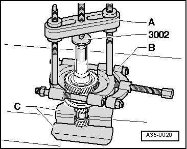
| t | Thrust piece -3002- |
| t | Thrust piece -T10080- |
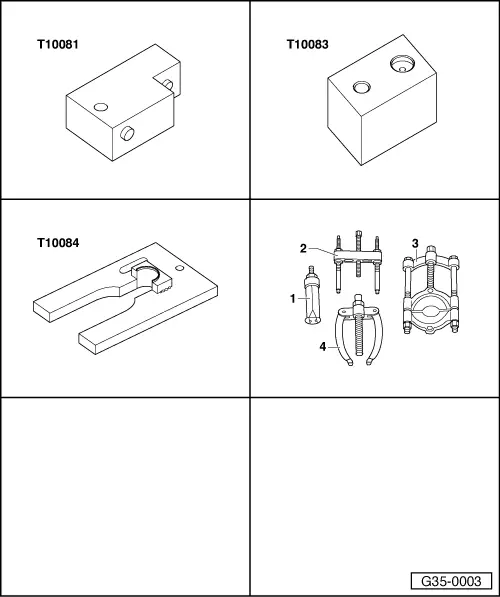
| t | Thrust piece -T10081- |
| t | Thrust block -T10083- |
| t | Thrust plate -T10084 A- |
| t | -1-Internal puller 30...37 mm, e.g. -Kukko 21/5- |
| t | -2-puller, e.g. -Kukko 18/1- |
| t | -3-Splitter 12...75 mm, e.g. -Kukko 17/1- |
| t | -4-Counter support, e.g. -Kukko 22/1- |
 Note
Note| t | Refer to technical data when installing new gears → Chapter. |
| t | Lubricate all bearings, selector gears and synchro-rings on input shaft with gear oil before installing. |
| t | Do not interchange synchro-rings. When re-using synchro-rings, always fit on the same selector gear. |
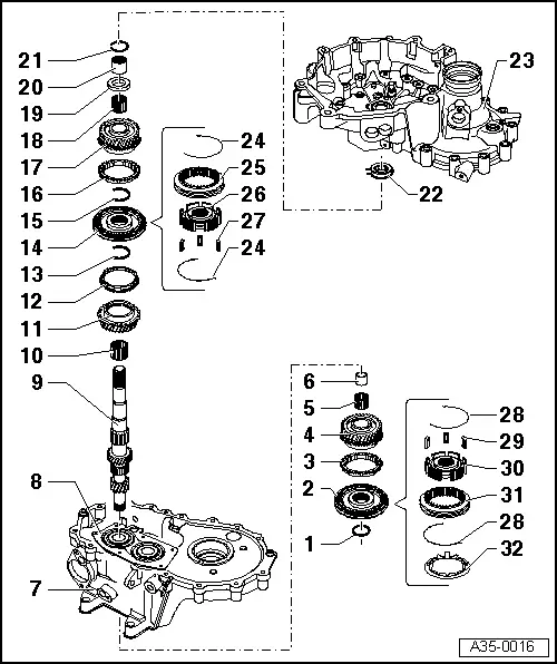
| 1 - | Circlip |
| q | Always renew |
| q | Determining thickness → Anchor |
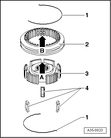
| 2 - | Locking collar with synchronising hub for 5th gear |
| q | Removing and installing ⇒ from Page → Chapter |
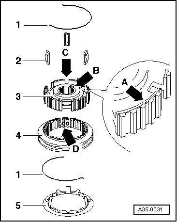
| q | Dismantling → Fig. |
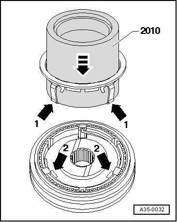
| q | Assembling 5th gear locking collar/synchronising hub → Fig. → Fig. |
| q | Installation position → Fig. |
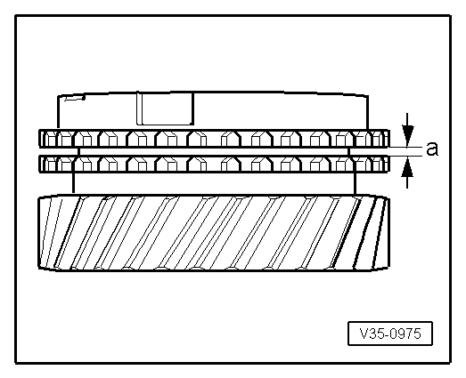
| 3 - | 5th gear synchro-ring |
| q | Checking for wear → Fig. |
| 4 - | 5th speed selector gear |
| 5 - | Needle bearing |
| q | For 5th gear |
| q | Renew together with → Item |
| 6 - | Sleeve |
| q | For 5th gear needle bearing |
| q | Renew together with → Item |
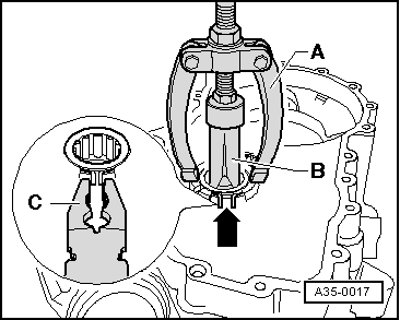
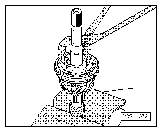
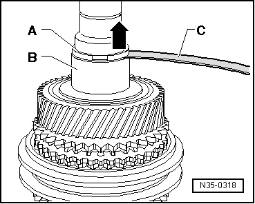
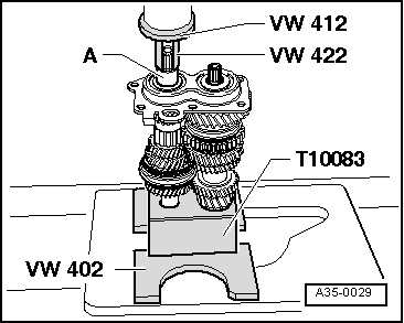
| q | Press off with bearing mounting/grooved ball bearing → Fig.. |
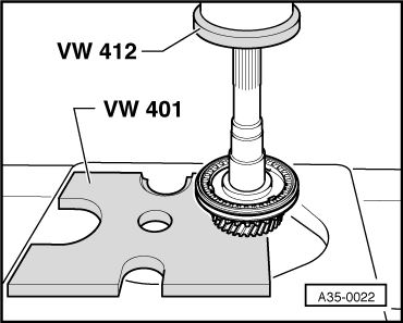
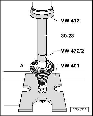
| q | Pressing on → Fig. |
| 7 - | Gearbox housing |
| 8 - | Bearing mounting with grooved ball bearings |
| q | If bearing mounting is separated from gearbox housing, it must always be renewed |
| q | Only renew grooved ball bearings together with bearing mounting. |
| q | Pressing off → Fig. |
| q | Pressing on → Fig. |
| 9 - | Input shaft |
| 10 - | Needle bearing |
| q | For 3rd gear |
| 11 - | 3rd speed selector gear |
| 12 - | 3rd gear synchro-ring |
| q | Checking for wear → Fig. |
| 13 - | Circlip |
| q | Fitted on gearboxes with code letters EYX and FDM |
| q | Modification: not fitted from 07.01 onwards |
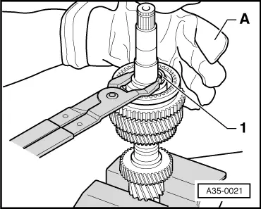
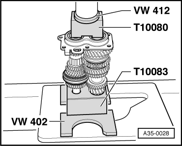
| q | Pressing out → Fig. |
| q | Fitting → Fig. |
| 14 - | Locking collar with synchronising hub for 3rd and 4th gear |
| q | Press off with 3rd speed selector gear → Fig. |
| q | Dismantling → Fig. |
| q | Installation position: Locking collar/synchronising hub → Fig. |
| q | Assembling → Fig. |
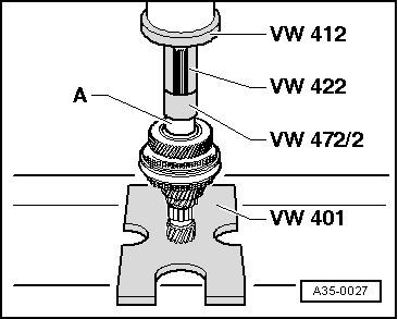
| q | Pressing on → Fig. |
| 15 - | Circlip |
| q | Fitted on gearboxes with code letters EYX and FDM |
| q | Modification: not fitted from 07.01 onwards |
| q | Pressing out → Fig. |
| q | Fitting → Fig. |
| 16 - | 4th gear synchro-ring |
| q | Checking for wear → Fig. |
| 17 - | 4th speed selector gear |
| 18 - | Needle bearing |
| q | For 4th gear |
| q | Modification: from 07.01 onwards, needle bearing is fitted with additional sleeve; allocate via → Electronic parts catalogue |
| q | Pressing off sleeve for needle bearing → Anchor |
| q | Pressing on sleeve for needle bearing → Fig. |
| 19 - | Thrust washer |
| 20 - | Inner race for roller bearing |
| q | Pull off together with 3rd speed selector gear → Fig. |
| q | Pressing on → Fig. |
| 21 - | Circlip |
| q | Renew |
| q | Determining thickness → Fig. |
| 22 - | Roller bearing |
| q | With circlip |
| q | Pulling out → Fig. |
| q | Pressing in → Fig. |
| q | Installation position: Circlip in bearing faces towards input shaft |
| 23 - | Clutch housing |
| 24 - | Spring |
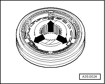
| q | Installation position → Fig. |
| 25 - | Locking collar for 3rd and 4th gear |
| 26 - | Synchronising hub for 3rd and 4th gear |
| 27 - | Locking pieces (3x) |
| 28 - | Spring |
| q | Installation position → Fig. |
| 29 - | Locking pieces (3x) |
| 30 - | 5th gear synchronising hub |
| 31 - | 5th gear locking collar |
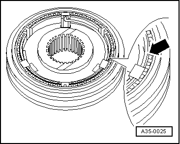
| 32 - | Check ring |
| q | Prevents locking pieces from moving out |
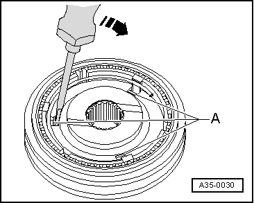
| q | Removing → Fig. |
| q | Installing → Fig. |
|
|
|
|
Note |
|
|
|
|
|
 WARNING
|
|
|
|
|
|
|
|
|
|
| Gap -a- | Installation depth | Wear limit |
| 3rd, 4th and 5th gear | 1.1 ... 1.7 mm | 0.5 mm |
|
|
|
|
|
|
|
|
|
|
| Measured value (mm) | Circlip thickness (mm) | Axial clearance (mm) |
| 0.05…0.10 | 2.0 | 0.05…0.15 |
| 0.15…0.20 | 2.1 | 0.05…0.15 |
| 0.25…0.30 | 2.2 | 0.05…0.15 |
| 0.35…0.40 | 2.3 | 0.05…0.15 |
| 0.45…0.50 | 2.4 | 0.05…0.10 |
Note
|
|
|
|
|
|
|
|
|
|
|
|
|