
A2
| Dismantling and assembling output shaft |

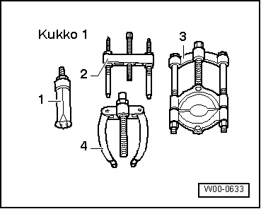
| Special tools and workshop equipment required |
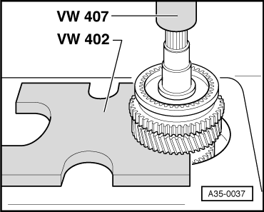
| t | Thrust plate -VW 402- |
| t | Press tool -VW 407- |
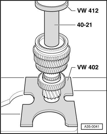
| t | Press tool -VW 412- |
| t | Tube -VW 415 A- |
| t | Press tool -VW 432- |
| t | Drift sleeve -40 - 21- |
|
|
|
|
 Note
Note| t | Refer to technical data → Chapter when installing new gears or a new output shaft. |
| t | Lubricate all bearings, selector gears and synchro-rings on output shaft with gear oil before installing. |
| t | Do not interchange synchro-rings. When re-using synchro-rings, always fit on the same selector gear. |

| 1 - | Clutch housing |
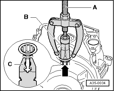
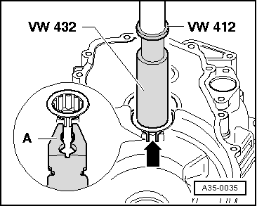
| 2 - | Roller bearing |
| q | With circlip |
| q | Pulling out → Fig. |
| q | Pressing in → Fig. |
| q | Installation position: the circlip in the bearing faces the output shaft |
| 3 - | Output shaft |
| q | If an inner race has been fitted as bearing seat for roller bearing → Item, it is not possible to detach it from output shaft. |
| q | Check bearing seat / roller bearing inner race for scoring or other damage. |
| q | If you detect scoring or other damage to the bearing seat / inner race, renew both output shaft and roller bearing. |
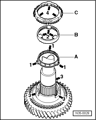
| 4 - | 4th gear wheel |
| q | Installation position: Collar faces 3rd gear → Fig. |
| 5 - | Circlip |
| 6 - | Circlip |
| 7 - | 3rd gear wheel |
| q | Installation position: Collar faces 4th gear → Fig. |
| 8 - | Circlip |
| 9 - | 2nd speed selector gear |
| 10 - | Needle bearing |
| q | For 2nd gear |
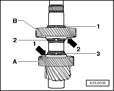
| 11 - | Inner ring for 2nd gear |
| q | Checking for wear → Fig. |
| q | Installation position → Fig. |
| 12 - | Outer ring for 2nd gear |
| q | Fit on inner ring → Item |
| q | Renew if scored or if there are visible traces of wear |
| q | Installation position → Fig. |
| 13 - | 2nd gear synchro-ring |
| q | Checking for wear → Fig. |
| q | Installation position → Fig. |
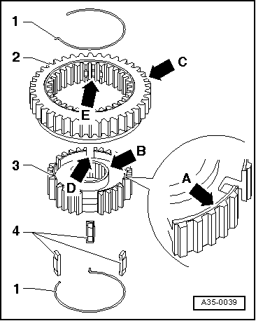
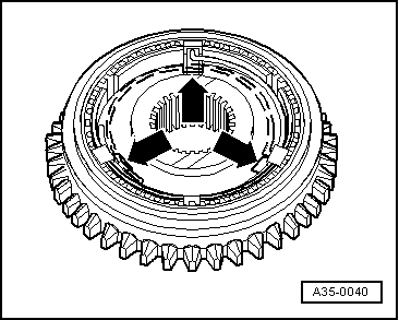
| 14 - | Locking collar with synchronising hub for 1st and 2nd gear |
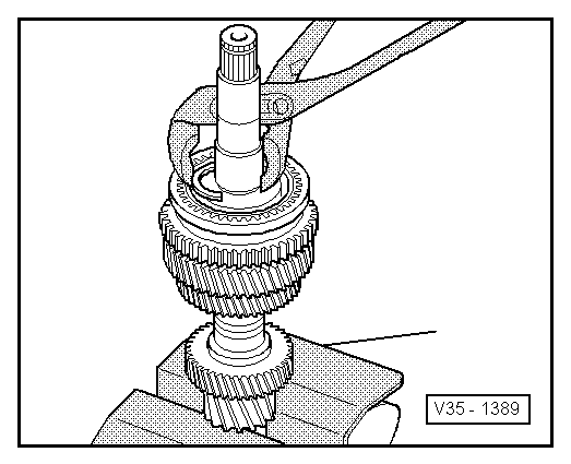
| q | Press off together with 2nd speed selector gear after removing circlip → Item → Fig. |
| q | Dismantling → Fig. |
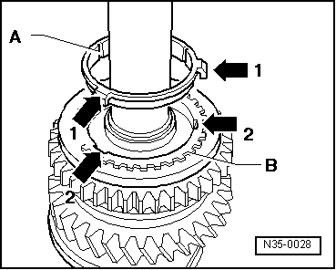
| q | Assembling locking collar/synchronising hub → Fig. and → Fig. |
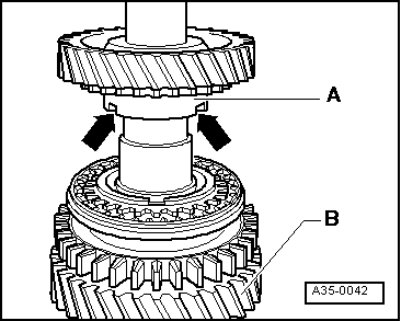
| q | Installation position → Fig. |
| q | Pressing on → Fig. |
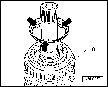
| 15 - | Circlip |
| q | Pressing out → Fig. |
| q | Fitting → Fig. |
| 16 - | 1st gear synchro-ring |
| q | Checking for wear → Fig. |
| q | Assemble so that the recesses engage on the locking pieces on the locking collar → Item |
| 17 - | Outer ring for 1st gear |
| q | Insert in synchro-ring → Item; installation position → Fig. |
| q | Renew if scored or if there are visible traces of wear |
| 18 - | Inner ring for 1st gear |
| q | Checking for wear → Fig. |
| q | Check lugs for scoring |
| q | Installation position → Fig. |
| 19 - | Needle bearing |
| q | For 1st gear |
| 20 - | 1st speed selector gear |
| q | Installation position → Fig. |
| 21 - | Bearing mounting with grooved ball bearings |
| q | Only renew grooved ball bearings together with bearing mounting. |
| q | If bearing mounting is separated from gearbox housing, it must always be renewed |
| q | Pressing off → Fig. |
| q | Pressing on → Fig. |
| 22 - | Gearbox housing |
| 23 - | 5th gear wheel |
| q | Installation position: Collar faces gearbox housing cover ⇒ Page → |
| 24 - | Circlip |
| q | Always renew |
| q | Determining thickness → Anchor |
| 25 - | Spring |
| q | Installation position → Fig. |
| 26 - | Locking collar |
| 27 - | Synchronising hub |
| 28 - | Locking pieces (3x) |
|
|
|
|
 WARNING
|
|
|
|
|
|
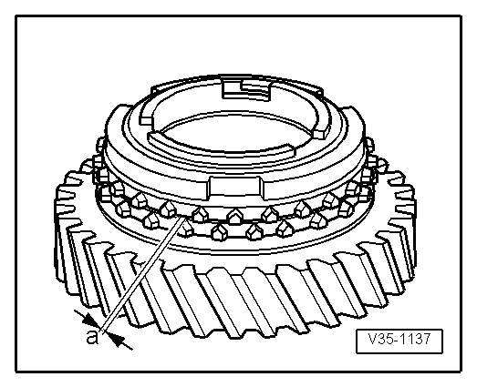
| Gap -a- | Installation depth | Wear limit |
| 1st and 2nd gear | 0.75 ... 1.25 mm | 0.3 mm |
|
|
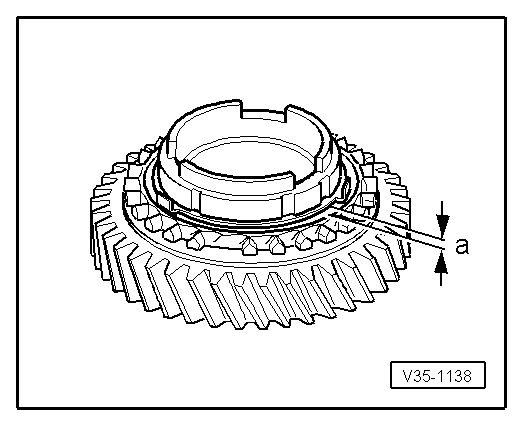
| Gap -a- | Installation depth | Wear limit |
| 1st and 2nd gear | 1.2 ... 1.8 mm | 0.5 mm |
|
|
|
|
|
|
|
|
|
|
|
|
|
|
|
|