audi Workshop Repair Guides

Audi Workshop Service and Repair Manuals

Turbocharger for vehicles with engine code letters ATL, BHC - exploded view > < Turbocharger for vehicles with code letters AMF - exploded view
Removing and installing turbocharger - vehicles with engine code letters AMF
Special tools and workshop equipment required
   
t  
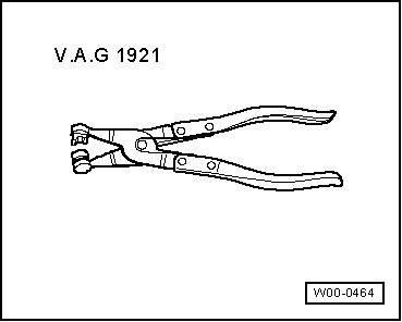
Hose clip pliers -V.A.G 1921-
Removing
  Caution
If the turbocharger has suffered mechanical damage (e.g. damaged compressor wheel), it is not sufficient merely to fit a new turbocharger. The following work must be performed in order to avoid further damage:
t  Check air cleaner housing, air filter element and air intake hoses for dirt and foreign particles.
t  Check the entire charge air system (including the charge air cooler) for foreign matter.
t  If foreign matter is found in the charge air system, clean all relevant ducts and hoses and renew charge air cooler if necessary.
  W00-0464
–  Remove bonnet → Chapter.
–  If fitted, unclip bracket -1-.
–  Take off engine cover panel -arrows-.
–  Remove noise insulation beneath cover.
  A10-0812
–  Lever off caps -3 and 4- on two-piece windscreen wiper arm with a screwdriver.
–  Slacken nuts on two-piece windscreen wiper arm a few turns.
–  Release arms -1 and 2- one after the other by tilting them slightly on the wiper shafts.
–  Remove nuts completely and take off two-piece windscreen wiper arm.
  Note
Use puller (commercially available) to remove wiper arm if necessary.
  A92-10019
–  Disconnect washer fluid hose -3-.
–  If fitted, unplug electrical connectors -4 and 5- for heated washer jets.
–  Open hose clip -6- using hose clip pliers -V.A.G 1921- and detach water drain hose from cowl panel grille.
–  Pull off rubber seal -1- on cowl panel grille.
–  Disconnect cowl panel grille -2-.
  A92-0166
–  Unscrew nuts and bolts -arrows-.
–  Pull fresh air duct forwards and remove by turning it to right side of vehicle.
  A92-0054
–  Detach air hose -2- at mechanical exhaust recirculation valve.
–  Disconnect vacuum hose -3- at mechanical exhaust gas recirculation valve.
–  Disconnect vacuum hose -4- from vacuum unit for intake manifold flap.
  Note
Disregard -item 1-.
  A23-10163
–  Remove air intake hose -2- from charge air cooler.
  Note
Disregard -item 1-.
  A10-0830
–  Detach air intake hose -1- at air mass meter -G70-.
–  Unplug electrical connector -3- at air mass meter -G70-.
–  Remove nut -2-.
–  Disconnect crankcase breather hose -4- at cylinder head cover.
–  Move aside fuel lines at air pipe.
  Note
The air pipe remains in the vehicle.
–  Remove front right wheel.
–  Remove catalytic converter → Chapter.
  A10-1753
–  Unbolt heat shield for drive shaft (left-side) -arrows-.
  A10-0843
–  Unbolt bracket for air pipe from sump -arrows-.
  A17-0430
–  Detach air intake hose -6- from turbocharger.
–  Remove oil return pipe by unscrewing nuts -2- and union nut -1-.
–  Detach charge pressure control hose -5- at turbocharger and at vacuum unit for charge pressure control.
–  Disconnect breather hose -4-.
–  Unscrew bolts -3- and detach air pipe from turbocharger.
  Note
The air pipe remains in the vehicle.
  A21-10117
–  Slacken bolt -1- approx. 3 turns.
–  Unbolt oil supply pipe -3- from turbocharger and move clear to one side.
  Note
Disregard -item 2-.
  A21-10182
–  Remove nut (bottom) -arrow- for turbocharger.
–  Lift out air hose (previously disconnected from below) from turbocharger and pull out upwards.
  A21-10195
–  Remove heat shield for exhaust manifold -arrows-.
  A21-0308
–  Remove connecting pipe for exhaust gas recirculation -item 1 and 2-.
  A26-10518
–  Unscrew bolts -arrows- and remove intake manifold.
  A23-10124
–  Remove both bolts -arrows- for turbocharger (hold turbocharger in position).
–  Place turbocharger on subframe.
–  Take out turbocharger downwards.
Installing
Installation is carried out in the reverse order; note the following:
  Note
t  Renew gaskets, seals and self-locking nuts.
t  Fill turbocharger with engine oil at connection for oil supply pipe.
t  Charge air system must be free of leaks.
t  Hose connections and hoses for charge air system must be free of oil and grease before assembly.
t  Secure all hose connections with the correct type of hose clips (same as original equipment) → Parts catalogue.
–  Install intake manifold → Rep. Gr.23.
–  Install connecting pipe for exhaust gas recirculation (first tighten loosely and then tighten connections to specified torque).
–  Install catalytic converter → Chapter.
–  Install air pipes/hoses with plug-in connectors → Chapter.
–  Install windscreen wiper arm → Rep. Gr.92.
–  Check oil level → Chapter.
  Note
After installing turbocharger, allow engine to idle for approx. 1 minute and do not rev up immediately to ensure turbocharger is supplied with oil.
Tightening torques
  A21-10196
ComponentNm
Turbocharger to exhaust manifold25 1)
Heat shield to exhaust manifold22
Oil return pipe to:Cylinder block30
Turbocharger15
Oil supply pipe to turbocharger22
Air pipe to:Turbocharger8
Sump8
Body8
Drive shaft heat shield to cylinder block33
Engine cover panel to bracket5.5
l  1) Renew nuts.


Turbocharger for vehicles with engine code letters ATL, BHC - exploded view > < Turbocharger for vehicles with code letters AMF - exploded view