
A2
|
|
|
|
|
 Caution
|
|
 Note
Note
|
|
Note
|
|
|
|
|
|
Note
|
|
|
|
|
|
|
|
|
|
|
|
|
|
|
|
Note
|
|
|
|
Note
|
|
|
|
|
|
|
|
|
|
Note
|
|
Note
Note
|
|
| Component | Nm | |||
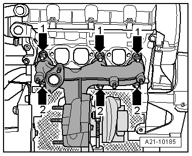
| Turbocharger to cylinder head | 25 1) | |||
| Heat shield to turbocharger | 22 | |||
| Support for turbocharger to cylinder block | 25 | |||
| Oil return pipe to cylinder block | 30 | |||
| Oil supply pipe to: | Turbocharger | 22 | ||
| Oil filter bracket | 22 | |||
| Exhaust gas recirculation cooler to: | Mechanical exhaust gas recirculation valve | 22 | ||
| Intake manifold | 20 | |||
| Turbocharger | 22 1) | |||
| Intake manifold flap motor -V157- to mechanical exhaust gas recirculation valve | 10 | |||
| Air pipe to: | Turbocharger | 8 | ||
| Sump | 8 | |||
| Body | 8 | |||
| Drive shaft heat shield to cylinder block | 33 | |||
| Engine cover panel to bracket | 5.5 | |||
| ||||