audi Workshop Repair Guides

Audi Workshop Service and Repair Manuals

Removing and installing coupling drive toothed belt > < Checking valve timing
Removing and installing main drive toothed belt
Special tools and workshop equipment required
   
t  Camshaft lock -T10016-
  W00-0594
Removing
–  Detach bonnet → Chapter.
–  Remove poly V-belt → Chapter.
–  Release retaining clips -arrows- and detach cover (top) for toothed belt.
  A13-10528
–  Rotate crankshaft in normal direction of rotation to „TDC“.
l  Notch on crankshaft pulley must align with edge of marking -O-.
  N13-0451
l  The locating holes in the camshaft sprockets must align with the corresponding holes in the camshaft housing -arrows-.
  Note
If the locating holes are positioned on the opposite side, the crankshaft must be turned one revolution further.
  N13-0155
–  Insert locking pins -D- on camshaft lock -T10016- all the way into locating holes in camshaft housing as follows:
l  Through locating hole in inlet camshaft sprocket -C-.
l  Through locating hole in exhaust camshaft sprocket.
l  The knobs on locking pins must be on a level -line A-.
–  Push retainer -B- onto inlet camshaft sprocket as far as stop.
–  Remove engine mounting → Chapter.
  Caution
Risk of damage to engine.
t  To prevent the crankshaft sprocket from slipping off the drive lug, do not rotate the crankshaft after the poly V-belt pulley has been detached.
t  Secure crankshaft sprocket with bolt and 2 washers before turning crankshaft.
–  Remove poly V-belt pulley for crankshaft → Chapter.
  N13-0369
–  Remove bolts -arrows- and loosen retaining clips -1- to detach toothed belt cover (bottom).
  A13-10529
–  Remove bolts -arrows- and detach engine support -1-.
  A13-10530
–  Check „TDC“ position of crankshaft:
l  The flat tooth on crankshaft sprocket -1- must align with marking -arrow- on oil pump housing.
  Note
Disregard item -2-.
  N17-0076
  Caution
If a used belt runs in the opposite direction when it is refitted, this can cause breakage.
Before removing, mark direction of rotation of toothed belt with chalk or felt-tipped pen for re-installation.
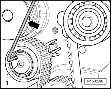
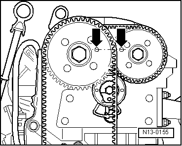
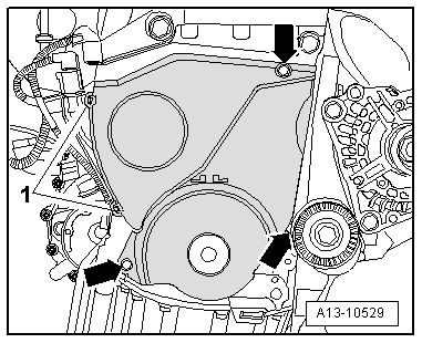
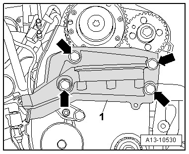
–  Loosen bolt -1- for main drive tensioning roller.
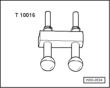
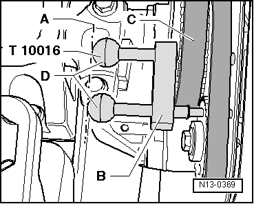
–  Detach camshaft lock -T10016-.
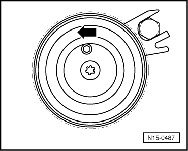
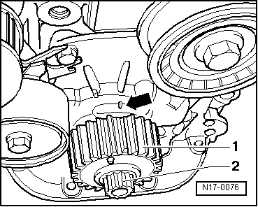
–  Use an Allen key to turn tensioning roller in anti-clockwise direction -arrow- and detach toothed belt.
  Note
t  Camshaft lock -T10016- must be fitted again if further repair work has to be performed on the cylinder head or valve gear.
t  If the toothed belt is re-installed immediately, attach camshaft lock -T10016- after installing the toothed belt.
  N15-0590
Installing
l  Tightening torques → Chapter
Installation is carried out in the reverse order; note the following:
–  Install tensioning roller for main drive (if removed) and turn anti-clockwise to position shown -arrow- using Allen key.
  N15-0487
–  Tighten bolt for main drive tensioning roller hand-tight.
l  Bolt -2- for oil pump housing must engage in the recess in base plate -1-.
  Note
Disregard items marked -3- and -arrows-.
  Note
  A13-10577
Note the marking for direction of rotation when reinstalling a used toothed belt.
–  Fit main drive toothed belt -B- in the sequence coolant pump, tensioning roller, crankshaft and inlet camshaft.
A - Coupling drive toothed belt
  N13-0150
–  Insert locking pins -D- on camshaft lock -T10016- all the way into locating holes in camshaft housing once again.
  N13-0369
–  To tension toothed belt, turn tensioning roller in clockwise direction -arrow A- until indicator -3- aligns with notch -arrow B- in base plate -1-.
–  Tighten bolt for main drive tensioning roller.
–  Remove camshaft lock -T10016-.
–  Turn crankshaft 2 revolutions in direction of engine rotation and set to „TDC“ once again.
  A13-10577
–  Check „TDC“ position of crankshaft:
l  The flat tooth on crankshaft sprocket -1- must align with marking -arrow- on oil pump housing.
  Note
Disregard item -2-.
  N17-0076
l  The locating holes in the camshaft sprockets must align with the corresponding holes in the camshaft housing -arrows-.
  N13-0155
–  Check that locking pins -D- on camshaft lock -T10016- can again be inserted all the way into locating holes in camshaft housing as follows:
l  Through locating hole in inlet camshaft sprocket -C-.
l  Through locating hole in exhaust camshaft sprocket.
–  Repeat adjustment procedure if holes do not align → Anchor.
Remaining installation steps are carried out in reverse sequence; note the following:
–  Install poly V-belt pulley for crankshaft → Chapter.
–  Install engine mountings → Chapter.
  N13-0369

Removing and installing coupling drive toothed belt > < Checking valve timing