audi Workshop Repair Guides

Audi Workshop Service and Repair Manuals

Checking intake manifold pressure sender > < Testing accelerator position senders
MM-MPI injection and ignition system (4-cylinder)
Checking components
Checking throttle valve control part

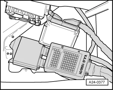
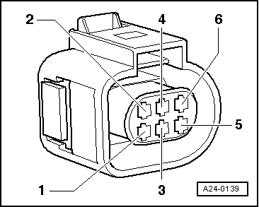
Components of throttle valve control part (J338):
Throttle valve drive (G186), angle sender 1 for throttle valve drive (G187) and angle sender 2 for throttle valve drive (G188).

Note:

If the throttle valve control part is replaced, the new control part must without fail be adapted to the engine control unit .

On vehicles fitted with an automatic gearbox the gearbox control unit must also be adapted:

=> Self-diagnosis for automatic gearbox 001; Repair group 01; Performing self-diagnosis

Special tools, workshop equipment, testers, measuring instruments and auxiliary items required

  • ◆ Test box V.A.G 1598/31
  • ◆ Hand multimeter V.A.G 1526 or multimeter V.A.G 1715
  • ◆ Adapter set V.A.G 1594
  • ◆ Current flow diagram

Test conditions

  • ● Throttle valve not damaged or dirty.

Test sequence

 
A24-0377
  • ‒ → Connect test box V.A.G 1598/31 to control unit wiring harness. The engine control unit remains disconnected => Page 24-8.
  • ‒ Measure resistance of throttle valve drive between contacts 117 + 118 on test box
        Specification: 3...200 ω

If the specification is not obtained:

  • ‒ Replace throttle valve control part (J338).

If the specification is obtained:

  • ‒ Check voltage supply of throttle valve control part and wiring to control unit => Page 24-50.
 
A24-0139

If the voltage supply and wiring is OK:

  • ‒ Renew engine control unit => Page 24-126.

Checking voltage supply and wiring to control unit

  • ‒ → Pull the 6-pin connector off the throttle valve control part.
  • ‒ Connect the multimeter to measure voltage to contacts 2 + 6 of the connector.
  • ‒ Switch on ignition.
        Specification: min. 4.5 V
  • ‒ Switch off ignition.
  • ‒ Connect the multimeter to measure voltage to contact 2 of the connector and earth.
  • ‒ Switch on ignition.
        Specification: min. 4.5 V
  • ‒ Switch off ignition.

If the specifications are not attained:

 
A24-0377
  • ‒ → Connect test box V.A.G 1598/31 to control unit wiring harness. The engine control unit remains disconnected => Page 24-8.
  • ‒ Check wiring for open circuit between test box and connector using current flow diagram:
        Contact 1+socket 92
        Contact 2+socket 83
        Contact 3+socket 117
        Contact 4+socket 84
        Contact 5+socket 118
        Contact 6+socket 91
        Wire resistance: max. 1.5 ω
  • ‒ Additionally check wires for short to one another.
  • ‒ Additionally check the wiring for short to battery positive or earth.

If no fault is detected in the wiring:

  • ‒ Check engine control unit voltage supply => Page 24-121.

Checking intake manifold pressure sender > < Testing accelerator position senders