-
‒ Enter "062" for Display Group 062 and confirm entry with Q key.
-
‒ Check display values for electronic throttle potentiometer voltages.
|
|
|---|
|
|
Display zones
|
|
|
1
|
2
|
3
|
4
|
|
Display Group 062: Electronic throttle potentiometer voltages
|
|
Display
|
xx %
|
xx %
|
xx %
|
xx %
|
|
Indicates
|
Throttle valve angle
(angle sender 1)
|
Throttle valve angle
(angle sender 2)
|
Accelerator position
sender
|
Accelerator position
sender 2
|
|
Range
|
0 ... 100 %
|
100...0 %
|
0 ... 100 %
|
0 ... 100 %
|
|
Specification
|
3...100 %
|
3...100 %
|
12...97 %
|
12...97 %
|
Note:
The engine control unit converts the voltage readings from the angle senders into percentages of 5 V and displays them as percentages. (A supply voltage of 5 V is equivalent to 100%.)
-
‒ Observe display zones 3 and 4.
-
‒ Slowly depress accelerator to full throttle position.
The percentage value in display zone 3 should rise steadily between 12 and 97 % but without covering the full range of values.
The percentage value in display zone 4 should also rise steadily but without covering the full range of values (12...97 %).
If the display values do not appear as described:
-
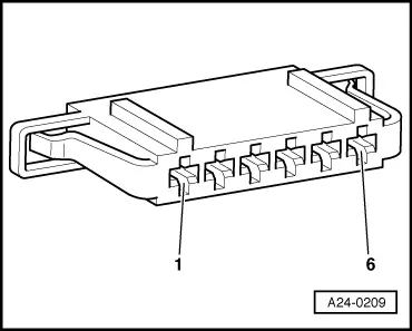
‒ Check whether connector of accelerator pedal position has become detached, is not properly engaged or if the contacts of the connector are corroded.
-
‒ Test voltage supply and wiring to accelerator position senders
.
Testing voltage supply
-
‒ Remove storage compartment on driver's side.
=> General body repairs, Interior; Repair group 68; Storage compartments, covers and trim; Removing driver's storage compartment
-
‒ Unplug connector for accelerator position sender.
-
‒ Switch ignition on.
|