
A2
|
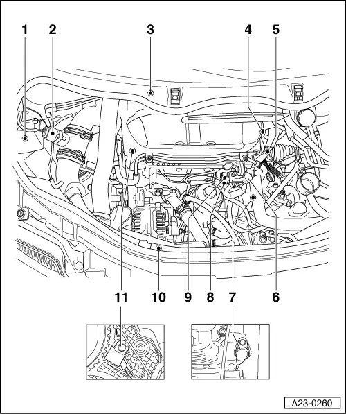
| 1 - | Exhaust gas recirculation valve -N18- and charge pressure control solenoid valve -N75- |
| 2 - | Air mass meter -G70- |
| 3 - | Exhaust gas recirculation valve |
| q | With intake manifold flap |
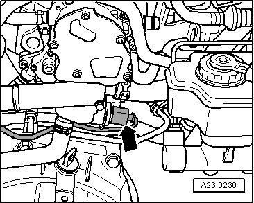
| 4 - | Coolant temperature sender -G62- |
| q | Fitting location → Fig. |
| 5 - | Connector |
| q | For unit injectors |
| 6 - | Fuel temperature sender -G81- |
| 7 - | Engine speed sender -G28- |
| 8 - | Grey connector |
| q | For engine speed sender -G28- |
| 9 - | Black connector |
| q | For Hall sender -G40-, for camshaft position |
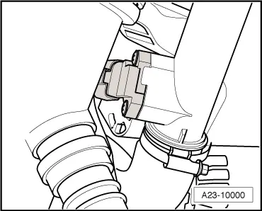
| 10 - | Intake manifold pressure sender -G71- with intake manifold temperature sender -G72- (BHC) |
| q | Engine code ATL → Fig. |
| 11 - | Hall sender -G40- |
| q | For camshaft position |
| A - | Brake pedal switch -F47- |
| q | In footwell on brake pedal |
| B - | Brake light switch -F- |
| q | In footwell on brake pedal |
| C - | Accelerator position sender -G79- |
| q | In footwell on accelerator → Fuel supply system - diesel engines; Repair group 20; Servicing accelerator mechanism |
| D - | Diesel direct injection system control unit -J248- |
| q | With altitude sender -F96- |
| q | Renewing control unit → Chapter |
| E - | Glow plug relay -J52- |
| q | Only for engine code BHC |
| q | Fitting location → Fig., → Fig. |
| F - | Automatic glow period control unit -J179- |
| q | Only for engine code ATL |
| q | Fitting location → Fig., → Fig. |
| G - | Terminal 30 voltage supply relay -J317- |
| H - | Auxiliary air heater control unit -J604- |
| q | Located in additional electric PTC heater |
|

|
|
|
|
|
|
|
|
|