audi Workshop Repair Guides

Audi Workshop Service and Repair Manuals

Checking outer constant velocity joint > < Grease quantity and type
Dismantling and assembling drive shaft
   
Dismantling and assembling drive shaft
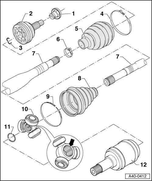
1 - Hexagon socket nut (pressed-steel version), 30 Nm
q   Always renew
q   Colour: black
2 - Outer constant velocity joint
q   Renew only as complete unit
q   Removing → Fig.
q   Installing: drive onto shaft as far as stop using plastic hammer
q   Greasing → Chapter
q   Checking → Chapter
q   Apply locking fluid D 185 400 A2 to splines before inserting in wheel hub → Anchor
3 - Circlip
q   Renew
q   Insert in groove on shaft
4 - Hose clip
q   Renew
q   Use clamp tensioner -V.A.G 1682- to tighten → Fig.
5 - Boot for constant velocity joint
q   Check for splits and chafing
q   Material: Hytrel (polyelastomer)
6 - Hose clip
q   Renew
q   Tightening → Fig.
7 - Drive shaft
8 - Boot
q   Check for splits and chafing
9 - Hose clip
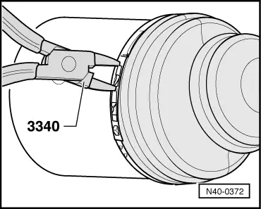
q   Releasing and installing → Fig.
10 - Triple roller spider with rollers
Chamfer -arrow- faces towards drive shaft splines
q   Pressing off → Fig.
q   Installation position → Fig.
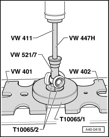
q   Pressing on → Fig.
11 - Circlip
q   Renew
q   Insert in groove on shaft
12 - Flange shaft for triple roller joint
q   Is bolted to gearbox
q   Removing and installing → 5-speed manual gearbox 085 DS; Rep. Gr.39

   
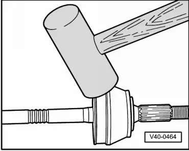
Removing outer constant velocity joint
–  Drive joint off drive shaft with a firm blow from an aluminium hammer.
  V40-0464
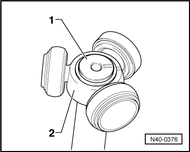
Installation position of triple roller spider
–  Before pressing off triple roller spider, mark position of triple roller spider -2- in relation to drive shaft -1-.
Use a waterproof felt-tip pen for marking.
  N40-0376
Pressing triple roller spider off drive shaft.
  N40-0444
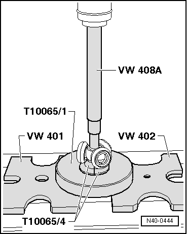
Pressing triple roller spider onto drive shaft
Chamfer on spider faces towards shaft and is used as an assembly aid.
–  Fit triple roller spider onto shaft according to markings and press home onto stop.
  A40-0416
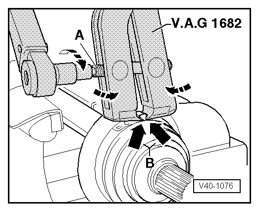
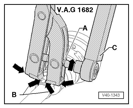
Tightening hose clip on outer joint (large diameter)
–  Apply clamp tensioner -V.A.G 1682- as shown. Ensure jaws of tool make contact with lugs -arrows B- on hose clip.
–  Tighten hose clip by turning spindle with torque wrench (take care to keep clamp tensioner straight).
  Note!
t  Due to the hard material of the CV joint boot (as opposed to rubber), a stainless steel hose clip is required; this can only be tightened using clamp tensioner -V.A.G 1682-.
t  Tightening torque: 20 Nm.
t  Use torque wrench-C- (adjustment range 5 ... 50 Nm), e.g. -V.A.G 1331-.
t  Make sure thread of spindle -A- on clamp tensioner moves freely. Lubricate with MOS2 grease if necessary.
t  If the thread is stiff (e.g. due to dirt), the required clamping force will not be attained at the hose clip when applying the specified tightening torque.
  V40-1076
Tightening hose clip on outer joint (small diameter)
  V40-1343
Releasing and installing hose clip
  N40-0372

Checking outer constant velocity joint > < Grease quantity and type