audi Workshop Repair Guides

Audi Workshop Service and Repair Manuals

Detaching and fitting Bowden cables from/on heater control > < Heating, heater control and air ducts
Heating, Air Conditioner
Servicing heating
Removing and installing heater control

Notes:

  • ◆ Different types of the heater controls:

=> Parts List

    • ‒ For vehicles up to and including model year 2000.
    • ‒ For vehicles as of model year 2001 (with switch for heated rear window).
    • ‒ For vehicles without or with map-controlled engine cooling.
  • ◆ The illumination of the rotary control is with a bulb in the type which was installed up to and including model year 2000 (at start of production). Later, the lighting was changed to LEDs. These can no longer be replaced.
 
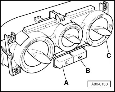
A80-0138
  • ◆ → To ensure misted windows are demisted as quickly as possible, recirculated air mode is not possible with "air distribution to windscreen". The control unit switches off the air recirculation mode approx. 15° before the rotary switch for air distribution -C- reaches its final position (air to windscreen) and the switch-on telltale in switch -B- goes out. If the rotary switch is turned back again, the heating remains in fresh air mode (this applies to all heater control designs).
  • ◆ The rotary switches and switches on the heater control are illuminated via terminals 58s and 58d.

=> Current Flow Diagrams, Electrical Fault-Finding and Fitting Locations

Notes on the type which are installed into vehicles as of model year 2001:

 
A80-0138
  • ◆ → In vehicles as of model year 2001 a heater control is installed in which the switch for the heated rear window -A- is installed.
    Note the following:
    • ‒ In these vehicles, the heated rear window is switched on via a relay which is controlled by the control unit installed in the heater control.

=> Current Flow Diagrams, Electrical Fault-Finding and Fitting Locations

 
A80-0138
    • ‒ → The control unit switches off the heated rear window after a heating period of approx. 15 minutes and the switch-on telltale in switch -A- goes out.
    • ‒ If the voltage on the control unit for the heated rear window falls below 9V, the heated rear window remains switched off until it is above 10 V again.
    • ‒ When the heated rear window is switched on, the telltale in switch -A- is lit.
    • ‒ When the air recirculation mode is selected, the telltale in switch -B- is lit.
    • ‒ The control unit for the heated rear window and fresh-air/recirculated air switchover and the lamps (LEDs = light emitting diodes) for illuminating the switches and rotary switches may not be replaced individually.
    • ‒ If the ignition is switched off and then back on again, the heated rear window remains switched off and the heating changes to or remains in fresh air mode.

Notes for vehicles with map-controlled cooling

 
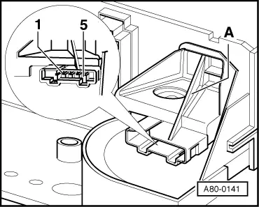
A80-0141
  • ◆ → A heater control with an additional electrical component -A- is installed in vehicles with map-controlled cooling. Switch -F269 for temperature selection rotary knob and potentiometer -G267 for temperature selection rotary knob are installed in this component (potentiometer = variable resistance).

=> Parts List

 
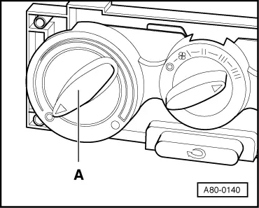
A80-0140
  • ◆ → Two-way valve -N147 is actuated via switch -F269 (contacts 1 and 2) if rotary temperature switch -A- is at "cold" stop. This then switches vacuum through to refrigerant shut-off valve and the refrigerant shut-off valve shuts off the flow of refrigerant through the heat exchanger in heater.
  • ◆ The resistance of potentiometer -G267 is approx. 1000 ohms between contacts 3 and 5 and between 100 and 900 ohms between contacts 4 and 3 / 5 (depending on rotary switch setting).
 
A80-0141
  • ◆ → The rotary switch setting is transmitted to the engine control unit via potentiometer -G267 (contacts 3, 4 and 5). This setting affects the characteristic curve in the engine control unit for actuation of the thermostat -F265 for map-controlled cooling (e.g. if the engine is running at part throttle, the refrigerant temperature is controlled such that the temperature of the air emanating from the vents when the heater is in operation (rotary temperature switch set to heat) does not exceed that in vehicles without map-controlled cooling).
  • ‒ A refrigerant thermostat is installed in vehicles with map-controlled cooling; an additional electrical actuator is integrated in this thermostat. This actuator (thermostat -F265 for map-controlled engine cooling) is actuated by the engine control unit according to the current engine load and the rotary temperature switch setting.

=> Relevant Workshop Manual Injection and Ignition system

=> Relevant Workshop Manual Automatic Gearbox, Repair group 13

  • ‒ Actuation of thermostat -F265 alters the refrigerant temperature (the refrigerant thermostat opens at a higher temperature when the engine is running at part throttle in comparison to full engine throttle).

Removing

 
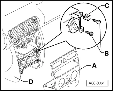
A80-0061
  • ‒ Remove radio.

=> Electrical System; Repair group 91; Repairing radio; Removing and installing radio

  • ‒ Remove panel for dash panel centre section -A-.

=> General Body Repairs Interior; Repair group 68; Shelves and trays/covers; Removing and installing front part of centre console

  • ‒ → Remove screws -B-.
  • ‒ Removing centre section of dash panel:

=> General Body Repairs Interior; Repair group 68; Shelves and trays/covers; Removing and installing front part of centre console

Installing

Installation is carried out in the reverse order, when doing this note the following:

  • ‒ When installing, ensure that the spring clips -C- are in the correct position.

Detaching and fitting Bowden cables from/on heater control > < Heating, heater control and air ducts