
Removing and Installing Bevel Box - Gearbox Mechanics and Operation
|
|
|
|
|
|
|
|
|
|
|
 Note
Note |
|
|
|
 Caution
|
|
|
|
Note
Note
Note |
|
Note
|
|
|
|
|
|
|
|
|
|
| Component | Nm | |||||||
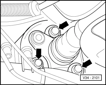
| Bevel box to gearbox | 40 + 45° 1)2) | |||||||
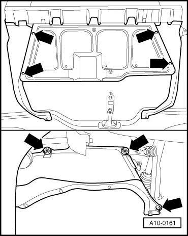
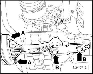
| Pendulum support to | gearbox | 40 + 90° 1)3) | ||||||
| subframe | 20 + 90° 1)3) | |||||||
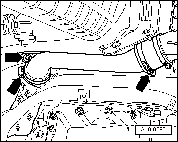
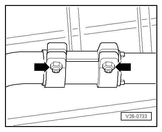
| Air pipe to longitudinal member | 10 | |||||||
| ||||||||