| –
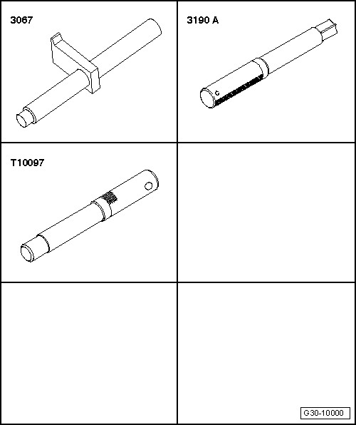
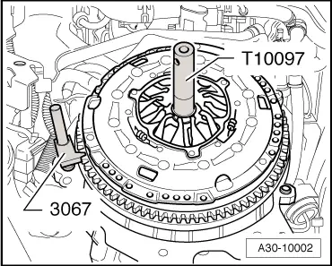
| Apply counter-hold tool -3067- in order to loosen bolts. |
| To prevent the pressure plate from becoming distorted during removal (causes clutch grab when driving off), always adhere to the following procedure when unbolting the pressure plate: |
| –
| Working clockwise, loosen all six bolts consecutively in steps of 90° (1/4 turn) until the pressure plate is released. |
| –
| Take off pressure plate and clutch plate. |
| Installation is carried out in reverse sequence; note the following: |

Note | t
| Renew clutch plate and pressure plate if riveted joints are damaged or loose. |
| t
| If required, always renew clutch plate and pressure plate together. |
| t
| Select the correct clutch plate and pressure plate according to engine code: → Parts catalogue. |
| t
| If the clutch has burnt out, thoroughly clean the bell housing, flywheel and parts of the engine facing the gearbox in order to prevent odours. |
| t
| Clean input shaft splines and (in the case of a used clutch plate) the hub splines. Remove corrosion and apply only a very thin coating of grease for clutch plate splines -G 000 100- to the splines. Then move clutch plate backwards and forwards on input shaft until hub moves freely on shaft. It is important to remove excess grease. |
| t
| Pressure plates have an anti-corrosion coating and are greased. Only the contact surface may be cleaned, otherwise the service life of the clutch will be considerably reduced. |
| t
| Pressure plate contact surface and clutch plate lining must make full contact with flywheel. Only then insert bolts. |
| –
| Note correct installation position of clutch plate: |
| l
| The marking “Getriebeseite” (gearbox side) faces towards the gearbox |
|
|
|