audi Workshop Repair Guides

Audi Workshop Service and Repair Manuals

List of selectable functions > < Safety precautions
Connecting vehicle diagnostic, testing and information systemVAS 505x and selecting functions
Connecting vehicle diagnostic, testing and information system -VAS 505x- and selecting functions
Procedure
l  Selector lever in position “P” or “N” and handbrake applied.
l  Vehicle voltage supply OK.
l  Fuses OK → Current flow diagrams, Electrical fault finding and Fitting locations
l  Earth connections for gearbox OK.
–  Check earth connections for corrosion and poor contact, repair if necessary → Current flow diagrams, Electrical fault finding and Fitting locations.
–  Check battery earth strap and earth strap between battery and gearbox.
   
Vehicles up to model year 1999:
–  Connect the vehicle diagnostic, testing and information system -VAS 505x- to the diagnostic connector using diagnostic cable with the ignition switched off.
  A01-0058
Vehicles from model year 2000 onwards:
–  Connect the vehicle diagnostic, testing and information system -VAS 505x- to the diagnostic connector using diagnostic cable with the ignition switched off.
All models:
  WARNING
Observe safety precautions → Chapter.
  Note
If a fault message appears on the display → Operating instructions for vehicle diagnostic, testing and information systemVAS 505x.
–  Switch on ignition.
or
–  Start engine.
  A01-0062
Display on -VAS 505x-:
–  From menu touch Vehicle self-diagnosis button -item 1-.
  A01-10029
Display on -VAS 505x-:
–  From menu -1-, select vehicle system “02 - Gearbox electronics” and advance by pressing button.
  Note
By selecting “General services” and advancing with the button, the diagnostic function “Interrogate fault memory - all fault menus” will be performed and then the fault memories of all vehicle systems with self-diagnosis capability will be interrogated.
–  Wait until next screen display appears.
  A01-10008
Display on -VAS 505x-:
2 - Control unit identification of gearbox control unit
  A87-0314
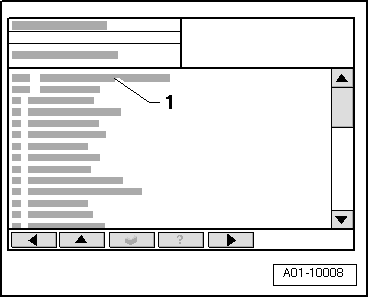
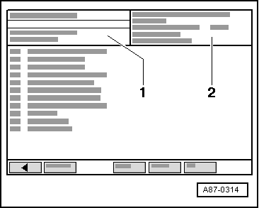
Control unit identification of gearbox control unit (example)
02 - Gearbox electronicsVehicle system
01M927733..Part No.; For correct version, refer to → Electronic parts catalogue
AG4 01MAutomatic 4-speed gearbox 01M
2029Control unit software version (data level)
00000Control unit coding (not required)
Workshop code 12345Workshop code of -VAS 5051B- which was used to perform the last coding

If readout “Vehicle system not available” appears in display zone -1-:
–  Check:
t  Voltage supply to diagnostic connector → Current flow diagrams, Electrical fault finding and Fitting locations.
t  Wiring connections from diagnostic connector to automatic gearbox control unit -J217- → Current flow diagrams, Electrical fault finding and Fitting locations.
   

List of selectable functions > < Safety precautions