audi Workshop Repair Guides

Audi Workshop Service and Repair Manuals

Removing and installing cooling system thermostat > < Draining and filling cooling system
4-cyl. Diesel Direct Injection Engine (TDI), Mech. Components
Removing and installing parts of the cooling system
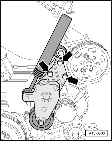
Removing and installing coolant pump
 
G19-0013

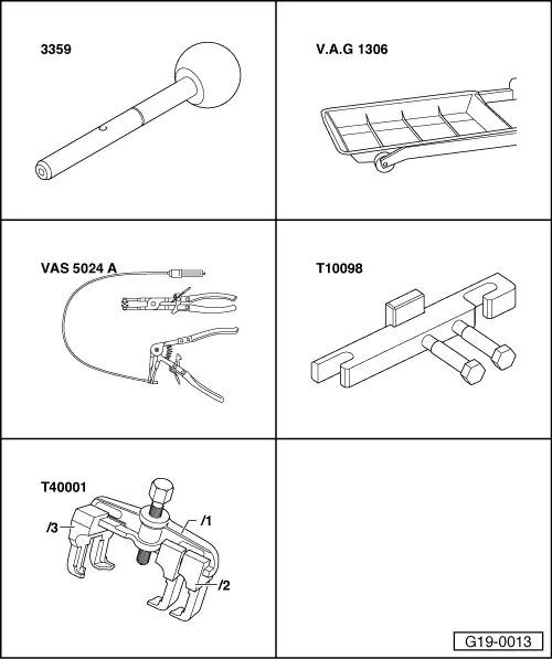
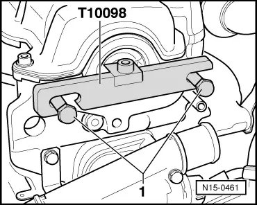
Special tools and workshop equipment required

  • ◆ Pin 3359
  • ◆ V.A.G 1306
  • ◆ VAS 5024 A
  • ◆ Camshaft straightedge T10098
  • ◆ Two-arm puller T40001
 
A10-1308

Removing

  • ‒ → Remove oil dipstick -1- from guide tube.
  • ‒ Unclip caps.
  • ‒ Unscrew nuts -arrows- and remove engine cover.
  • ‒ Reinsert oil dipstick in guide tube.
Important
Hot steam or hot coolant can escape when opening expansion tank. Cover cap with a cloth and open carefully.
  • ‒ Open the cover of the coolant expansion tank
 
A10-0396
  • ‒ → Remove lower air duct pipe -arrows-.
 
A37-0198
  • ‒ → Remove noise insulation in centre and on right -arrows-.
 
A10-0122

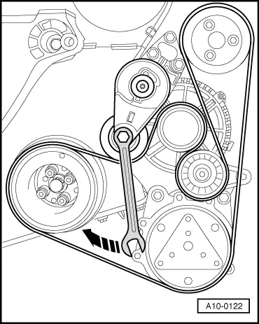
Note:

Mark the running direction with chalk or a felt-tipped pen before removing the ribbed belt. If the belt runs in the opposite direction when it is refitted, this can cause breakage.

  • ‒ Fit flat 16 mm ring spanner to hexagon of tensioner.
  • ‒ → Swivel tensioning roller in direction of arrow to slacken ribbed belt.
  • ‒ Remove ribbed belt.

 
A10-0118
  • ‒ Place drip tray V.A.G 1306 below engine.
  • ‒ → Turn drain plug -arrow- on radiator anti-clockwise. If necessary, fit drain hose on connection.
 
A10-0119
  • ‒ → Also disconnect lower coolant hose on oil cooler -arrow-, and drain off remaining coolant.

 
A13-0502
  • ‒ Detach the cover and the electrical connector at the right headlight unit.
  • ‒ → Disconnect fuel-feed line -2- and fuel-return line -1- at injection pump.
  • ‒ Disconnect the electrical connection -3- at the sender -G71/-G72.
  • ‒ Expose the wiring at the air duct pipe.
  • ‒ Remove the air duct pipe on right side -arrows-.
 
A13-0503
  • ‒ → Remove tensioner for ribbed belt -arrows-.
  • ‒ Remove upper toothed belt guard.

 
A10-0933
  • ‒ → Remove air duct hose -1- from air duct pipe.
  • ‒ Detach connector of air mass meter -3-.
  • ‒ Unscrew bolts -4- and -5-.
  • ‒ Remove vent hose -2- from rear of air cleaner housing.
  • ‒ Take out air cleaner housing.
 
A13-0045
  • ‒ → Turn crankshaft to TDC No. 1 cylinder -arrow- (vehicles with manual gearbox).

 
A13-0043
  • ‒ → Turn crankshaft to TDC No. 1 cylinder -arrow- (vehicles with automatic gearbox).

Note:

Position crankshaft to TDC No. 1 cylinder with engine removed.

 
N15-0461
  • ‒ Remove the exhauster => Fig.15-8.
  • ‒ → Turn the bolts -1- by hand up to stop into the cylinder head.
  • ‒ Lock the camshaft using camshaft straightedge T10098 as shown in the illustration.
  • ‒ If the camshaft straightedge T10098 cannot be inserted, rotate crankshaft 1 additional turn (360°).

 
A13-0052
  • ‒ → Lock injection pump sprocket using pin 3359.
  • ‒ Loosen injection pump sprocket securing bolts -arrows-.
 
A23-0044

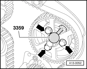
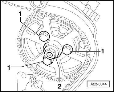
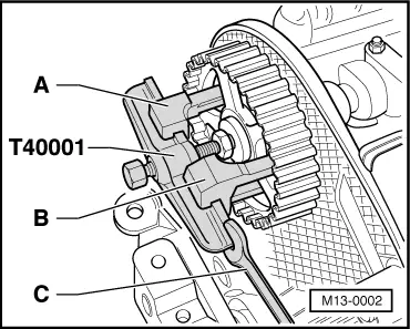
Note:

→ Never loosen the injection pump sprocket centre nut -2-. Otherwise the injection pump basic setting is incorrectly adjusted and cannot be corrected again using workshop equipment.

 
A13-0504
  • ‒ → Loosen the tensioning roller nut -arrow- by several turns.
 
M13-0002
  • ‒ Remove the toothed belt from the camshaft toothed belt sprocket.
  • ‒ → Unscrew the camshaft sprocket bolt by 1/2 turn .
  • ‒ Place the two-arm puller T40001 with claw T40001/2 -Item A- and the two-arm claw T40001/3 -Item B- centralised onto the camshaft sprocket.
  • ‒ Pull off the camshaft sprocket using the two-arm puller. Counterhold using an open-end spanner -C- in the process.
  • ‒ Remove camshaft toothed belt sprocket.
  • ‒ Remove the centre toothed belt guard.

Notes:

  • ◆ The vibration damper and bottom toothed belt guard do not have to be removed.
  • ◆ The toothed belt should be left in position on the crankshaft sprocket.
 
A19-0028
  • ‒ → Unscrew the bolt -1- and lay the idler roller -2- downwards.
  • ‒ Unscrew the bolts -3- and carefully guide the coolant pump -4- out towards rear between engine support and toothed belt guard.

Installing

Installation is carried out in the reverse order; note the following:

Notes:
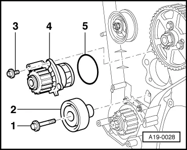
  • ◆ When performing installation procedures, replace seals and gaskets, as well as stretch bolts with specified tightening angle.
  • ◆ Hose connections and hoses for charge air system must be free of oil and grease before assembly.
  • ◆ Secure all hose connections with the correct hose clamps (same as original equipment):

=> Parts List

 
A19-0028
  • ‒ Clean and smooth down sealing surface for O- ring as required.
  • ‒ → Lightly coat new O-ring -5- with coolant G 012 A8 D.
  • ‒ Fit coolant pump -4-.
    • ‒ Installation position: Sealing plug in housing faces downwards.
  • ‒ Tighten bolts -3- for coolant pump to 15 Nm.
  • ‒ Replace idler roller bolt -1-, torque to 40 Nm and continue to turn 1/4 turn (90°).
  • ‒ Install toothed belt (adjust valve timing) => Page 13-31.

Note:

Observe all instructions on removing and installing the toothed belt =>from Page 13-23.

  • ‒ Install ribbed belt=> Page 13-10.
  • ‒ Top up coolant => Page 19-7.

Tightening torques

Component

Nm

Coolant pump to cylinder block

15

Idler wheel to cylinder block

40 + 90° 1)2)

    1)    Replace bolt

    2)    90°corresponds to a quarter of a turn

Removing and installing cooling system thermostat > < Draining and filling cooling system