Engine/gearbox assembly removed and attached to engine bracket -T10012-.
–
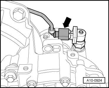
Unplug electrical connector -arrow- at speedometer sender -G22- on gearbox and release wiring from retainers, etc.
–
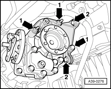
Unscrew bolts -1- and -2- from bracket on bevel box.
Note
Leave bracket in position. It cannot be removed at this stage.
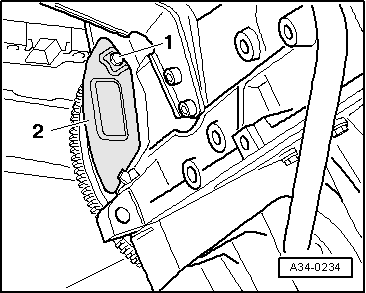
Note
The small cover plate -2- for the flywheel is located behind the bevel box and is not visible with the bevel box installed. Shown in illustration with gearbox removed.
–
Unscrew bolt -1- and lift out cover plate.
–
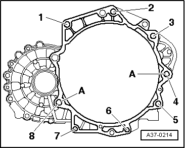
Remove engine/gearbox securing bolts -1 ... 8-.
–
Separate gearbox from engine.
Note
Second mechanic is required to separate engine/gearbox assembly.
 Note
Note