audi Workshop Repair Guides

Audi Workshop Service and Repair Manuals

Charge air cooling - exploded view > < Turbocharger - exploded view
Removing and installing turbocharger
Special tools and workshop equipment required
   
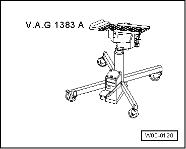
t  Engine and gearbox jack -V.A.G 1383 A-
t  8 mm hexagon socket wrench with ball head
Removing
  Note
t  Fit all heat insulation sleeves in the original position when installing.
t  All cable ties which are released or cut open when removing must be fitted in the same position when installing.
  W00-0120
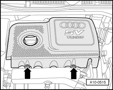
–  Take off engine cover panel -arrows-.
  WARNING
Hot steam or hot coolant can escape when expansion tank is opened; cover filler cap with cloth and open carefully.
–  Open filler cap on coolant expansion tank.
–  Remove front exhaust pipe → Chapter.
–  Drain off coolant → Chapter.
  A10-0515
–  Place drip tray for workshop hoist -VAS 6208- under engine.
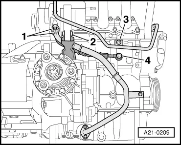
–  Disconnect coolant supply pipe -4- at cylinder block.
  Note
A large amount of coolant will escape.
–  Disconnect oil return pipe -1- from turbocharger.
–  Unbolt bracket -3- for coolant return pipe from cylinder block.
–  Loosen bolt -2- for turbocharger bracket approx. 2 turns; do not remove bolt.
  A21-0209
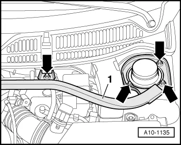
–  Remove cross piece -1- for suspension strut -arrows-, if fitted.
  A10-1135
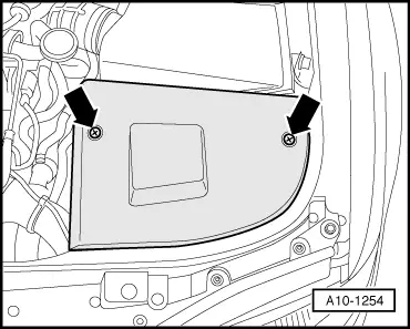
–  Remove front left cover -arrows-.
  A10-1254
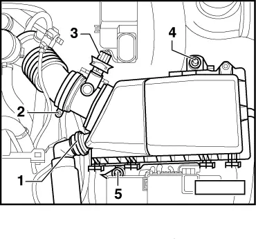
–  If fitted, detach air intake hose -1- leading to secondary air pump at air cleaner housing.
–  Release hose clip -2- and detach air intake hose from air mass meter -G70-.
–  Unplug electrical connector at air mass meter -G70- -item 3-.
–  Unscrew bolts -4- and -5- and remove air cleaner housing.
  A10-0443
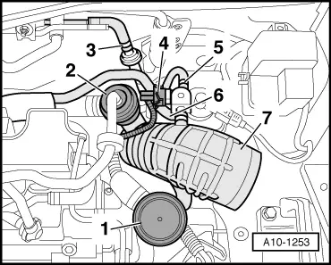
Detach air duct between air cleaner and turbocharger as follows:
–  Remove pressure control valve of crankcase breather -1- and mechanical air recirculation valve -2- from air duct.
–  Detach hose going to activated charcoal filter at non-return valve -3-.
–  Disconnect electrical connector -4- at charge pressure control solenoid valve -N75-.
–  Detach hoses -5- and -6- from charge pressure control solenoid valve -N75-.
–  Detach air duct -7- from connection on turbocharger and pull out hose -5-, guiding as required.
  A10-1253
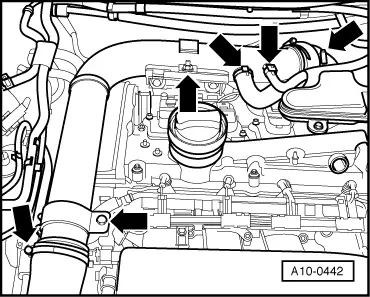
–  Remove air pipe -arrows-.
–  Detach air intake hose from turbocharger connection.
  A10-0442
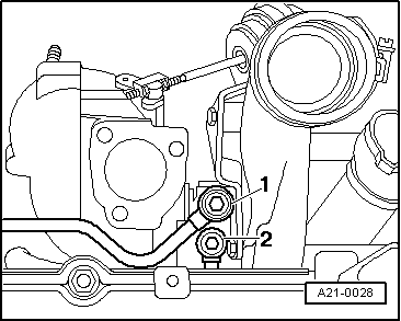
–  Disconnect coolant return pipe -1- from turbocharger using 8 mm hexagon socket wrench with ball joint.
  A21-0028
–  Unscrew bracket for oil supply pipe at turbocharger -arrows-.
  A21-0210
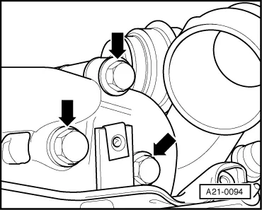
–  Unbolt turbocharger from exhaust manifold -arrows-.
–  Remove gasket between turbocharger and exhaust manifold and tilt turbocharger slightly away from engine.
  A21-0094
–  Disconnect oil supply pipe -2- from turbocharger using an 8 mm hexagon socket wrench with ball joint.
  A21-0028
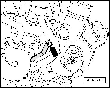
–  Remove bolt -arrow- on bracket for turbocharger.
–  Lower out turbocharger with coolant supply pipe connected.
Installing
Installation is carried out in the reverse order; note the following:
  Note
t  Renew gaskets, seals and self-locking nuts.
t  Fill turbocharger with engine oil at connection for oil supply pipe.
t  Hose connections and hoses for charge air system must be free of oil and grease before assembly.
t  Secure all hose connections with the correct type of hose clips (same as original equipment) → Parts catalogue.
t  Charge air system must be free of leaks.
t  Fit all heat insulation sleeves in the original position when installing.
t  Fit all cable ties in the original positions when installing.
–  Before installing turbocharger, connect coolant supply pipe and attach mounting bracket to turbocharger.
  A21-0211
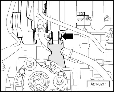
–  Move turbocharger into installation position from below and push onto bracket.
–  Tighten bolt hand-tight -arrow-.
  A21-0211
–  Secure oil supply pipe -2- to turbocharger.
–  Screw in banjo bolt -1- for coolant return pipe, but do not tighten.
  A21-0028
–  Secure bracket for oil supply pipe to turbocharger -arrow-.
–  Slide in gasket between exhaust manifold and turbocharger.
  A21-0210
–  Secure turbocharger to exhaust manifold (apply high-temperature paste to new bolts before fitting); high-temperature paste → Parts catalogue.
  A21-0094
–  Secure coolant return pipe -1-.
  A21-0028
–  Tighten bolt -2- of turbocharger bracket.
–  Secure oil return pipe -1- at turbocharger.
–  Secure bracket -3- for coolant return pipe to cylinder block.
–  Secure coolant supply pipe -4- to cylinder block.
  Note
When tightening connection for coolant supply pipe, make sure pipe going to turbocharger does not turn out of position.
–  Install front exhaust pipe → Chapter.
–  Install cross piece for suspension strut → Rep. Gr.40.
–  Check oil level → Chapter.
–  Fill cooling system → Anchor.
  Note
After installing turbocharger, allow engine to idle for approx. 1 minute and do not rev up immediately to ensure turbocharger is supplied with oil.
Tightening torques
  A21-0209
ComponentNm
Coolant supply pipe to:Turbocharger30
Cylinder block35
Mounting bracket for coolant supply pipe to turbocharger10
Coolant return pipe to:Turbocharger35
Cylinder block20
Oil supply pipe to turbocharger30
Bracket for oil supply pipe to turbocharger10
Oil return pipe to turbocharger10 1)
Turbocharger to exhaust manifold30 2)3)
Bracket for turbocharger to turbocharger30
Hose clips for air hoses3.5
l  1) Install using locking fluid; for locking fluid refer to → Parts catalogue.
l  2) Renew bolts.
l  3) Coat threads and contact surface of bolt heads with high-temperature paste; for high-temperature paste refer to → Parts catalogue.


Charge air cooling - exploded view > < Turbocharger - exploded view