audi Workshop Repair Guides

Audi Workshop Service and Repair Manuals

Coolant distributor housing - exploded view of components > < Performing diagnosis of map-controlled engine cooling system
Electrical test of map-controlled engine cooling system
   
Electrical test of map-controlled engine cooling system
Special tools and workshop equipment required
t  Hand-held multimeter -V.A.G 1526 A- or -V.A.G 1526 B-
t  Auxiliary measuring set -V.A.G 1594 A- or -V.A.G 1594 C-
t  Adapter cable, 121-pin -V.A.G 1598/31- (test box)

   
Test sequence
  WARNING
The radiator fan motors may start up.
  Note
Diagnosis of map-controlled engine cooling system has been performed → Chapter.
–  Take off engine cover panel -arrows-.
–  Start engine and run at idling speed.
  A10-0885
–  Unplug electrical connector -1- at coolant temperature sender -G62-.
  Note
Unplugging the connector from the coolant temperature sender -G62- causes the engine control unit to detect a fault in the map-controlled engine cooling system. It then constantly actuates the thermostat using full battery voltage.
–  Unplug connector -2- at map-controlled engine cooling thermostat -F265-.
  A26-0315
–  Connect multimeter (voltage test range) between contacts -1- and -2-.
l  Specification: Approx. battery voltage (after a short delay)
If specification is not obtained:
–  Connect multimeter to measure voltage between contact -1- and earth.
l  Specification: approx. battery voltage
–  Switch off ignition.
  A24-0331
If specification is not obtained:
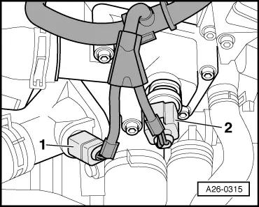
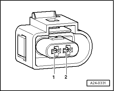
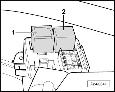
–  Check the wiring from contact 1 of the connector to the power supply relay for Simos control unit -J363--item 2- (below cover on left of bulkhead) for open circuit using the current flow diagram.
–  Repair wiring connection if necessary.
If no fault is found:
–  Connect adapter cable, 121-pin -V.A.G 1598/31- (test box) to connectors of wiring harness; do not connect engine control unit. Connect earth clip of test box to earth → Rep. Gr.24.
  Caution
To avoid damage to the electronic components, select the required measuring range and observe test conditions before connecting the test leads.
  A24-0341
–  Check for open circuit in the following wiring connection:
  A24-0331
Connector
Contact
Adapter cable, 121-pin -V.A.G 1598/31- (test box)
Socket
-2-116

–  Repair wiring connection if necessary.
If no fault is found:
–  Check function of thermostat → Chapter.
–  Plug in electrical connectors.
–  Interrogate and erase the fault memory for engine control unit, as faults are stored when the connectors are unplugged → Vehicle diagnosis, testing and information system VAS 5051.
   

Coolant distributor housing - exploded view of components > < Performing diagnosis of map-controlled engine cooling system