
A3 Mk1
|
 Note
Note
|
|
| Display zones | ||||
| 1 | 2 | 3 | 4 | |
| Display group 062: Electronic throttle potentiometer voltages | ||||
| Display | xx % | xx % | xx % | xx % |
| Display | Throttle valve angle (angle sender 1) | Throttle valve angle (angle sender 2) | Accelerator pedal position sender 1 | Accelerator pedal position sender 2 |
| Specification | 3...93 % | 97...3 % | 12...97 % | 4...49 % |
Note
Note
|
|
|
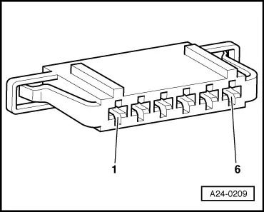
| Connector Contact | Specification |
| 1 + earth | approx. 5 V |
| 1 + 5 | approx. 5 V |
| 2 + earth | approx. 5 V |
| 2 + 3 | approx. 5 V |
|
|
|
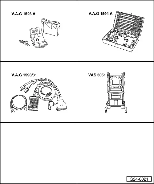
| Connector Contact | Test box -V.A.G 1598/31- Socket |
| 1 | 72 |
| 2 | 73 |
| 3 | 36 |
| 4 | 35 |
| 5 | 33 |
| 6 | 34 |
|