audi Workshop Repair Guides

Audi Workshop Service and Repair Manuals

Checking accelerator pedal position sender G79 > < Cleaning throttle valve module
Checking angle senders for throttle valve drive
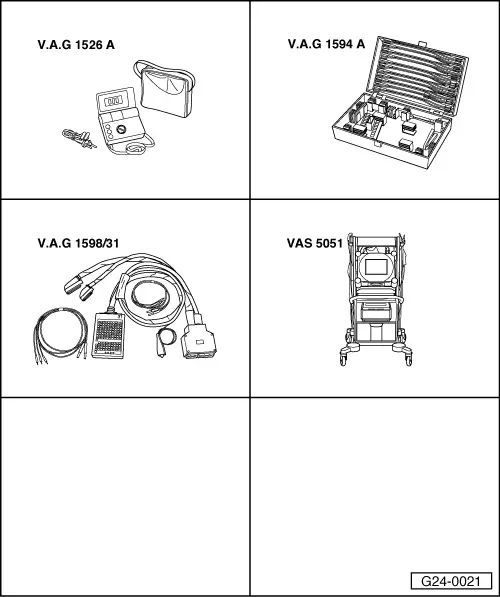
Special tools and workshop equipment required
t  -V.A.G 1526 A-
t  -V.A.G 1594 A-
t  -V.A.G 1598/31-
   
t  Vehicle diagnosis and service information system -VAS 5052-
Test sequence
–  Connect up the vehicle diagnostic and service information system -VAS 5052- and select the engine electronics control unit. When doing this, the ignition must be switched on.
–  Select the function “Read measured value block”.
–  Select “Display group number 062”.
–  Check the specifications for the electronic throttle potentiometer voltages in display zones 1 and 2.
  G24-0021
 Display zones
 1234
Display group 062: Electronic throttle potentiometer voltages
Displayxx %xx %xx %xx %
DisplayThrottle valve angle
(angle sender 1)
Throttle valve angle
(angle sender 2)
Accelerator pedal
position sender 1
Accelerator pedal
position sender 2
Specification3...93 %97...3 %12...97 %4...49 %

  Note
The engine control unit converts the voltage values of the angle senders into a percentage referenced to 5 V and displays these percentage values (5 V supply voltage corresponds to 100 %).
–  Observe display zones 1 and 2.
–  Slowly floor the accelerator pedal.
The percentage display in zone 1 must increase steadily. The tolerance range 3...93 % is not fully utilised in the process.
The percentage display in zone 2 must decrease steadily. The tolerance range 97...3 % is not fully utilised in the process.
  Note
t  The reason for the display in zone 1 increasing whereas the display in zone 2 decreases is the opposing action of the potentiometers (angle senders) in the throttle valve module.
t  This means that the voltage tapped at one of the angle senders approaches 5 V (the further the throttle valve is opened, the higher the voltage becomes and the percentage indicated increases).
t  The trend of the voltage tapped at angle sender 2 is away from 5 V and towards 0 V (the further the throttle valve is opened, the lower the voltage becomes and the percentage indicated decreases).
If the displays are not as described:
–  Check voltage supply and wiring to throttle valve module. Pay particular attention to the possibility of loose or corroded connectors.
–  Check the accelerator pedal position senders → Chapter.
Checking voltage supply of throttle valve module -J338-
–  Unplug the connector from the throttle valve module -J338-.
–  Switch on ignition.
   
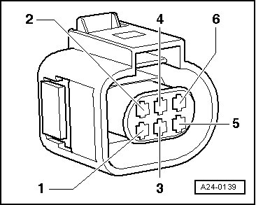
–  Connect up the multimeter (voltage measuring range) as follows:
  A24-0139
Connector
Contact
Specification
2 + earthapprox. 5 V
2 + 6approx. 5 V

If the readings do not match the specifications:
–  Check wiring between engine control unit and throttle valve module -J338-.
Checking wiring
   
–  Unplug the connector from the throttle valve module -J338-.
–  Connect the test box -V.A.G 1598/31- to the wiring harness to the engine control unit, but do not connect the actual engine control unit → Chapter.
–  Check for open circuit and short to earth or positive in the following wiring:
  A24-0139
Connector
Contact
Test box -V.A.G 1598/31-
Socket
192
283
3117
484
5118
691

–  Eliminate open circuit in wiring/short circuit if necessary.
If no fault is found in the wiring:
–  Replace the throttle valve module -J338-.
   

Checking accelerator pedal position sender G79 > < Cleaning throttle valve module