
A3 Mk1
 |
|
|
Work sequence
|
 |
|
|
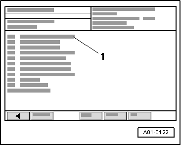
→ Display on VAS 5051:
|
 |
|
|
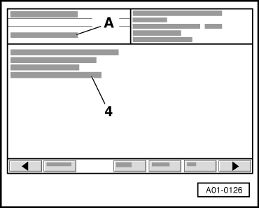
Activating exhaust gas recirculation valve → Display on VAS 5051:
Notes:
If the valve is not actuated (does not click):
=> 4-Cyl. TDI engine, Mechanics; Repair group 26; Exhaust gas recirculation system |
 |
|
|
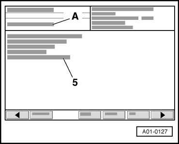
Activating air conditioner compressor shut-off
→ Display on VAS 5051:
If the conditioner compressor is not switched off:
Note: On vehicles without air conditioning this control element may be ignored. To continue the final control diagnostic, press the▸button. |
 |
|
|
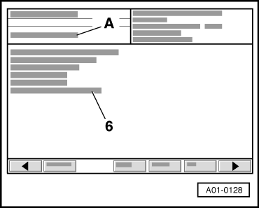
Activating charge pressure control solenoid valve
→ Display on VAS 5051:
Notes:
If the valve is not actuated (does not click):
=> 4-Cyl. TDI engine, Mechanics; Repair group 21; Charge air system with turbocharger |
 |
|
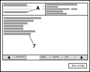
→ Display on VAS 5051:
Notes:
If the valve is not actuated (does not click):
=> 4-Cyl. TDI engine, Mechanics; Repair group 26; Exhaust gas recirculation system |
 |
|
|
Activating intake manifold flap motor
→ Display on VAS 5051:
If the engine does not stop:
|
 |
|
|
Activating glow period warning lamp
→ Display on VAS 5051:
If the warning lamp is not activated (does not flash):
|
 |
|
|
Activating radiator fan control
→ Display on VAS 5051:
If the fan does not run:
=> Current flow diagrams, Electrical fault finding and Fitting locations binder |
 |
|
|
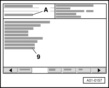
Activating glow plug relay
→ Display on VAS 5051:
If the relay does not click:
|
 |
|
|
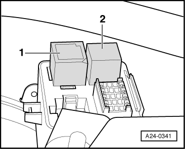
Only for vehicles with manual gearbox Activating low heat output relay
→ Display on VAS 5051:
|
 |
|
If the relay does not click:
=> Current flow diagrams, Electrical fault finding and Fitting locations binder |
 |
|
|
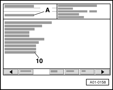
Only for vehicles with manual gearbox Activation of high heat output relay
→ Display on VAS 5051:
|
|
|
If the relay does not click:
=> Current flow diagrams, Electrical fault finding and Fitting locations binder |
 |
|
|
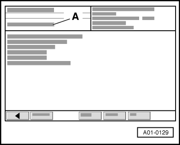
All models
→ Display on VAS 5051:
|