audi Workshop Repair Guides

Audi Workshop Service and Repair Manuals

Exploded view of subframe with final drive > < Removing and installing transverse link
Running gear, Front-wheel drive and four-wheel drive
Servicing rear axle - Four-wheel drive vehicles
Replacing wheel bearing
 
G42-0020

Special tools and workshop equipment required

  • ◆ Thrust plate 40-105
  • ◆ Puller 3423
  • ◆ Engine/gearbox lifter V.A.G 1383 A
  • ◆ Foot-operated pump with high-pressure hose V.A.G 1389 A/1
  • ◆ Hydraulic removal and installation device V.A.G 1459 B
  • ◆ Accessory set V.A.G 1459 B2
 
W00-0633
  • ◆ 2 - Kukko 18/0 puller

 
N45-0146

Sequence of operations

  • ‒ → Screw out bolt -1-.
  • ‒ Pull speed sensor out of trailing arm.
  • ‒ Remove drive shaft .
 
N42-0348
  • ‒ → Screw out bolts -1-.
  • ‒ Detach brake caliper and hang up with piece of wire.

Note:

Brake hose/pipe is never to be twisted or kinked.

  • ‒ Screw out cross-head bolt for brake disc and detach brake disc.

 
N42-0389

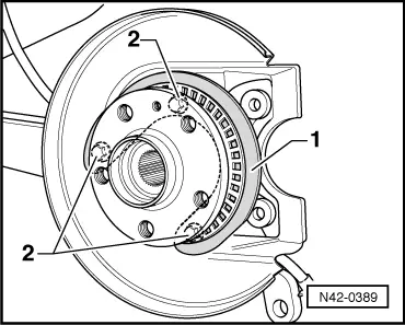
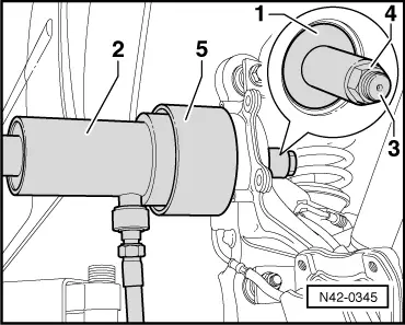
Pressing out wheel hub

  • ‒ → Insert thrust pad -1- as shown.
  •     1 -    Thrust pad E-39

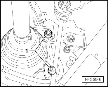
Note:

Position thrust pad such that it rests completely on bolt heads -2-.

 
N42-0342
  • ‒ → Fit centring device with clamp -2- at hollow plunger cylinder -1-.
  •     1 -    Hollow plunger cylinder HKZ-15 with thrust pad E-0-204-T, hydraulic
  •     2 -    Centring device with clamp E-76-2

 
N42-0343
  • ‒ → Fit bell -1-, hollow plunger cylinder -2- with pin -3- and special nut -4-.
  •     1 -    Bell E 40
  •     2 -    Hollow plunger cylinder HKZ-15
  •     3 -    Pin E-0-217
  •     4 -    Special nut E-8-214
  •     5 -    High-pressure hose with quick-release coupling
  •     6 -    Thrust pad E-39
  • ‒ Build up pressure with foot-operated pump.
  • ‒ Then check whether all tools are properly centred.
Attention:
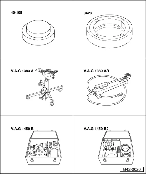
Place engine/gearbox lifter V.A.G 1383
  • ‒ Press wheel hub out of wheel bearing by way of pump action.
 
N42-0344

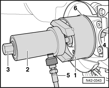
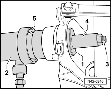
Pressing out wheel bearing

  • ‒ → Use commercially available circlip pliers to take out circlip -1-.
 
N42-0345
  • ‒ → Position thrust pad -1- on back of wheel bearing.
  • ‒ Place hollow plunger cylinder -2- with pin -3- and special nut -4- in position.
  • ‒ Build up pressure with foot-operated pump.
  • ‒ Then check whether all tools are properly centred.
  • ‒ Press out wheel bearing by way of pump action.
  •     1 -    Thrust pad E-5
  •     2 -    Hollow plunger cylinder HKZ-15
  •     3 -    Pin E-0-217
  •     4 -    Special nut E-8-214
  •     5 -    Bell E-44
 
A40-0140

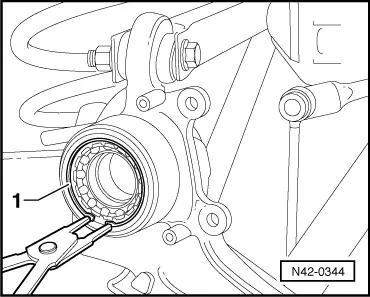
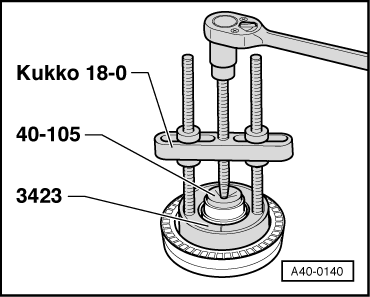
Detaching bearing inner race from wheel hub

  • ‒ → Apply special tools shown and extract bearing inner race by turning spindle.
 
N42-0346

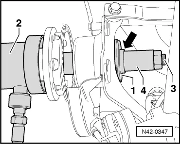
Pressing in wheel bearing

  • ‒ Place wheel bearing in position at wheel bearing housing.
  • ‒ → Position thrust pad -1- on back of wheel bearing housing.
  • ‒ Place hollow plunger cylinder -2- with pin -3-, special nut -4- and thrust pad in position.
  • ‒ Build up pressure with foot-operated pump.
  • ‒ Then check whether all tools are properly centred.
  • ‒ Press in wheel bearing by way of pump action.
  •     1 -    Thrust pad E-6-1
  •     2 -    Hollow plunger cylinder HKZ-15
  •     3 -    Pin E-0-217
  •     4 -    Special nut E-8-214
 
N42-0342
  •     5 -    Thrust pad E-13-1
  • ‒ Use pointed-nose pliers to insert circlip.

Pressing in wheel hub

  • ‒ Place wheel hub in position at wheel bearing.
  • ‒ → Fit centring device with clamp -2- at hollow plunger cylinder -1-.
 
N42-0347
  • ‒ → Position thrust pad -1- on back of wheel bearing housing.
  • ‒ Place hollow plunger cylinder -2- with pin -3-, special nut -4- and thrust pad in position.
  • ‒ Build up pressure with foot-operated pump.
  • ‒ Then check whether all tools are properly centred.
  • ‒ Press in wheel hub with foot-operated press.
  • Shoulder -arrow- of thrust pad E-5 must face special nut -4-.
  •     1 -    Thrust pad E-5
  •     2 -    Hollow plunger cylinder HKZ-15
  •     3 -    Pin E-0-217
  •     4 -    Special nut E-8-214

Perform further installation in reverse order, paying attention to the following:

  • ‒ Install drive shaft => Page 42-131.
  • ‒ Fit brake caliper.

=> Brake System; Repair Group 46

Exploded view of subframe with final drive > < Removing and installing transverse link