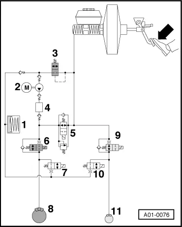
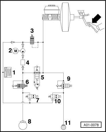
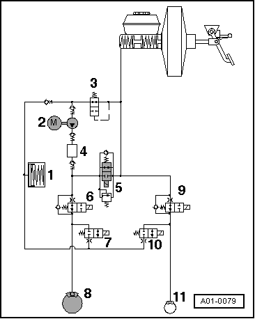
| Components of the ABS/EDL system |
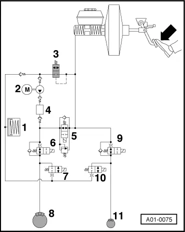
| The hydraulic circuit is a schematic diagram of the ABS/EDL system. The diagram shows only one brake circuit. |
| 1 - | Low pressure accumulator |
| 2 - | ABS hydraulic pump -V64- |
| 3 - | EDL inlet valve (hydraulic) |
| 4 - | Noise damping chamber |
| 5 - | EDL change-over/separating valve (electrical) with integrated pressure limiting valve |
| l
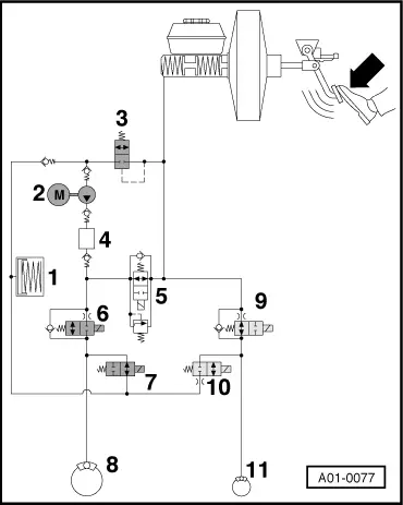
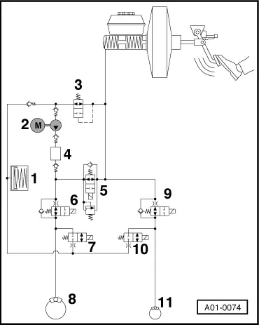
| The wheels are locked individually during final control diagnosis. For this test the mechanical and hydraulic components of the brake system must be working properly. This means that the master cylinder is able to build up pressure in all four wheel brake cylinders and there are no leaks in the hydraulic pipes, hoses and connections. |

Note | If one of the wheels does not lock, perform a visual inspection of the brake fluid reservoir, the master cylinder, the hydraulic unit and the wheel cylinders. |
| –
| Connect vehicle diagnostic, testing and information system -VAS 5051 A- → Chapter and select vehicle system “03 - Brake electronics”. When doing this the ignition must be switched on. |
|
|
|