audi Workshop Repair Guides

Audi Workshop Service and Repair Manuals

Removing and installing front brake caliper (RS 3) > < Servicing front brakes (RS 3)
Removing and installing front brake pads (RS 3)
Special tools and workshop equipment required
t  Piston resetting appliance -T10145-
  Note
Mark brake pads when removing them if they are to be reinstalled. Reinstall in their original position to prevent uneven braking.
Removing
–  Raise the vehicle.
–  Remove wheels.
  Note
The pad wear indicator wire is only installed at the left brake caliper.
   
–  Unclip pad wear indicator wire -9- from bracket.
  Note
Do not loosen bolts -2-.
–  Unplug electrical connector from pad wear indicator wire.
–  Press brake pistons at brake pads slightly back into brake caliper using a suitable tool.
  Note
Take care not to scratch or damage brake caliper.
  A46-10138
–  Pull pad wear indicator wire -9- out of retaining clip -10-.
–  Pull one brake pad retaining pin -11- out of brake caliper. While doing so, press down retaining clip -10-.
–  Pull second brake pad retaining pin -11- out of brake caliper.
–  Take brake pads out of brake caliper.
Use only methylated spirits to clean the brake caliper housing.
  WARNING
Brake fluid is poisonous and must NOT be drawn off by sucking through a hose. On account of its corrosive effect it must also not be allowed to come into contact with paintwork.
Installing
If provided, peel adhesive foil off back of brake pads.
Before fitting pads, clean guides and apply a thin coating of grease → ETKA.
Press back brake pistons using piston resetting appliance -T10145- when fitting new brake pads.
Make sure that no brake fluid escapes from brake fluid reservoir; otherwise components and paintwork will be damaged.
To draw off brake fluid from brake fluid reservoir use a bleeder bottle which is used only for brake fluid.
  WARNING
Brake fluid is poisonous and must NOT be drawn off by sucking through a hose. On account of its corrosive effect it must also not be allowed to come into contact with paintwork.
Perform further installation in reverse order; note the following:
–  Insert brake pads into brake caliper.
  Note
t  Make sure that brake pads are seated correctly.
t  The brake pads with the wear indicator wire are only fitted in the left brake caliper.
t  The pad wear indicator wire is fitted in the left brake caliper in both brake pads.
  A46-10138
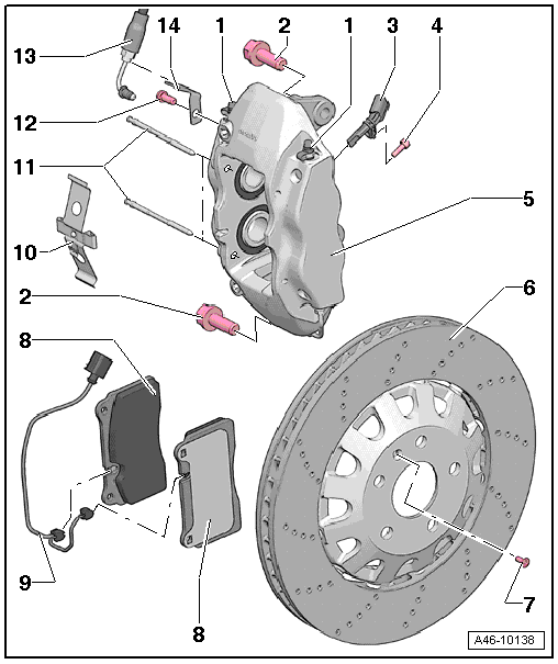
–  Slide one brake pad retaining pin -11- through brake caliper and brake pads from inside to outside.
–  Insert retaining spring -10- underneath retaining pin -11-.
–  Slide second retaining pin through brake caliper and brake pads from inside to outside. While doing so, press down retaining spring -10-.
  WARNING
Both brake pad retaining pins must be pressed through the brake caliper and the brake pads as far as the stop so that the spring is seated at the retaining pin in the brake caliper.
–  Insert pad wear indicator wire -9- in retaining spring -10-.
–  Connect pad wear indicator wire.
–  Insert pad wear indicator wire in bracket.
Fit wheels → Wheels and tyres; Rep. gr.44.
–  Lower vehicle.
–  Check brake fluid level and top up if necessary.
  WARNING
After installing the brake pads, depress pedal firmly several times with the vehicle stationary, so that the brake pads are properly seated in their normal operating position.
  WARNING
Before driving vehicle for the first time, make sure function of brakes is OK.
  A46-10138

Removing and installing front brake caliper (RS 3) > < Servicing front brakes (RS 3)