audi Workshop Repair Guides

Audi Workshop Service and Repair Manuals

Installing air conditioning unit > < Removing and installing air conditioning unit
Removing air conditioning unit
  Note
t  If necessary, obtain the radio anti-theft code before disconnecting the battery -A-.
t  On vehicles with electrically adjustable seats, move the seats to the rearmost position before disconnecting the battery -A- → General body repairs, interior; Rep. gr.72.
t  On removing bolts, note down bolt lengths and assignment for re-installation.
t  All cable ties and other wiring harness fasteners released or severed when removing the air conditioning unit are to be re-attached in the same position on fitting.
t  Depending on the vehicle equipment and the engine, the coolant hoses may be provided with thermal insulation. This must not be damaged and must be re-attached following installation.
–  Drain the refrigerant circuit: → Air conditioner with refrigerant R134a
–  Switch off ignition.
–  Place protective covers over driver's and front passenger's seats.
–  Disconnect the battery -A-. → Electrical system; Rep. gr.27
–  Dissipate the pressure in the coolant circuit by opening the cap at the coolant expansion tank → Engine, mechanics; Rep. gr.19.
   
–  Remove the components impeding access to the bolts of the refrigerant lines -A- at the expansion valve and to the coolant hoses to the heat exchanger in the engine compartment.
  Note
t  Depending on the engine and vehicle model, it may be necessary to unfasten or remove the following components: Top engine cover, compressed air pipe to throttle valve unit and intake manifold etc. → Engine, mechanics; Rep. gr.13.
t  On vehicles with 5-cyl. engine, remove the air pipe (from the air cleaner to the turbocharger) → Injection and ignition system; Rep. gr.24.
  A87-0666
t  Depending on the engine (e.g. on certain 2.0 l diesel engines depending on the exhaust system design), it may be necessary to remove the plenum chamber cover and the front wall of the plenum chamber -A- in order to be able to remove the heat shield and detach the refrigerant lines from the expansion valve as well as the coolant hoses to the heat exchanger → General body repairs, exterior; Rep. gr.55.
  A87-10683
t  There are different versions of the heat shield -B-. With version „1“, the speed nuts -A- have to be removed and the heat shield -B- detached from the vehicle.
  A87-10273
t  With version „2“, the clamping washers -A- and the clip -C- have to be removed and the heat shield -B- detached from the vehicle. After detaching the coolant hoses, remove the entire heat shield -B-.
t  For greater clarity, the illustrations show the heat shield -B- with the engine removed.
–  If fitted, detach the heat shield -B- from the front wall of the plenum chamber and the bulkhead and lay it aside (or remove it completely).
  A80-10000
–  If fitted, slide back the thermal insulation -D- and -E- so as to permit attachment for example of the hose clamps up to 40 mm -3093--F- to the coolant hoses -A- and -B-.
  A87-10269
–  Mark the positions of the coolant hoses -A- and -B-.
  Note
t  The heat exchanger is designed for a certain coolant flow direction. Care must therefore be taken to connect the coolant hoses correctly (coolant hose -A-: supply from cylinder head, coolant hose -B-: return to coolant pump).
t  The arrangement of the coolant hoses is identical for vehicles without air conditioner (heater only) and with air conditioner. This illustration shows the layout on a vehicle with air conditioner.
t  Bleeding coolant circuit → Engine, mechanics; Rep. gr.13.
–  If necessary, pinch off the breather hose (from the top connection -A- to the coolant expansion tank).
–  Cover the area beneath the connections for the coolant hoses -A- and -B- with absorbent paper, for example.
–  Pinch off the coolant hoses to the heat exchanger of the air conditioning unit (e.g. using hose clamps up to dia. 40 mm -3093-) and detach the hoses.
  A87-0674
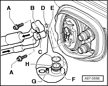
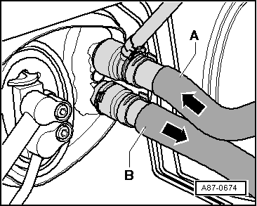
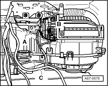
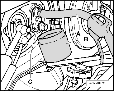
–  Attach a section of tubing -A- to the top connection.
–  Hold a vessel -B- beneath the bottom connection -C-.
–  Use a compressed-air gun to carefully blow the coolant out of the heat exchanger (into the vessel -B-).
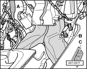
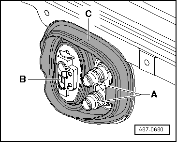
–  Detach the refrigerant lines from the expansion valve → Chapter and secure them (e.g. with a cable tie) such that they do not impede installation.
  Note
t  Seal open line connections (to prevent the ingress of dirt and moisture).
t  Use can be made, for example, for sealing open connections at the expansion valve or evaporator of the cap from a replacement expansion valve or replacement evaporator.
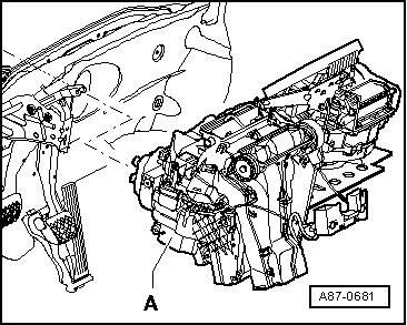
–  Remove the glove compartment, the storage compartment on the driver's side, the centre console and the dash panel: → General body repairs, interior; Rep. gr.70
  Note
So as not to damage the dash panel fascia, the dash panel is only to be placed on a clean workbench covered, for example, with clean cardboard.
–  Remove the accelerator pedal module → Fuel system; Rep. gr.20
  A87-0675
–  Remove the left and right vents -C-.
–  Fold the driver and passenger side floor covering to the rear to permit removal of the vents for the rear footwell -A- and -B- → General body repairs, interior; Rep. gr.70.
–  Remove both vents for the rear footwell -A- and -B-.
–  Remove the fresh-air blower → Chapter.
–  On vehicles with manually controlled air conditioner, remove the air conditioner controls (air conditioning system control unit -J301-) (do not remove the base plate for the controls) → Chapter.
–  Remove the dash panel and the dash panel cross member (central tube): → General body repairs, interior; Rep. gr.70
  A87-0677
–  Remove the control unit for the data bus diagnostic interface -J533- (attached in the area of the steering column to the holder -A-). → Electrical system; Rep. gr.90
–  Remove the bolts -B- and detach the holder -A- from the air conditioning unit (leave holder attached to wiring harness in vehicle).
  A87-0676
–  Remove both bolts -A- at the holder for the wiring harness -B-.
–  Unplug the connector -C-.
–  Detach the condensation drain from the air conditioning unit → Chapter.
–  Detach the fasteners of the vehicle wiring harness (e.g. cable ties) at the air conditioning unit.
–  On vehicles with electric supplementary heater (vehicles with diesel engine only), disconnect the power supply wiring from the supplementary air heater element -Z35- → Chapter.
–  Unplug all connectors between the vehicle wiring harness and the electrical components at the air conditioning unit.
  Note
The „air conditioner“ wiring harness is removed with the air conditioning unit.
  A87-0678
–  Carefully pull the right side of the air conditioning unit slightly to the rear (such that the bolt -B- at the right holder -A- can be slackened off).
  Note
  A87-0679
t  Only pull gently on the air conditioning unit so as not to break the holder -A-.
t  Slackening off the bolt -B- involves reaching between the air conditioning unit and the floor covering at the right wheel housing (fresh-air blower must be removed beforehand).
–  Remove the bolts -B- and detach the holder -A- from the air conditioning unit (leave holder attached to wiring harness in vehicle).
  A87-0679
–  Detach both flanges for the coolant pipes to the heat exchanger -A- and for the expansion valve (to the evaporator) -B- from the lead-throughs of the grommet -C-.
  Note
t  On removing the air conditioning unit, pay attention to both coolant pipes to the heat exchanger to ensure that they do not catch on the opening to the plenum chamber or on the noise insulation mat and become bent or damaged.
t  Pay attention to the wiring harness. Pulling too firmly could damage individual wires.
  A87-0680
–  Take out the air conditioning unit -A- towards the passenger side.
  A87-0681

Installing air conditioning unit > < Removing and installing air conditioning unit