audi Workshop Repair Guides

Audi Workshop Service and Repair Manuals

Replacing air conditioner compressor pulley > < Detaching air conditioner compressor from holder/attaching (vehicles with 5-cyl. engine)
Checking activation signal for air conditioner compressor regulating valveN280
Checking activation signal for air conditioner compressor regulating valve -N280-
Special tools and workshop equipment required
t  Adapter set -V.A.G 1594 C-
t  Vehicle diagnostic, testing and information system -VAS 5051 A- with probe -VAS 5051/8-
  Note
The following describes testing of a „Denso“ air conditioner compressor of type „7 SEU 16“. Checking is to be performed in the same manner for vehicles with a different type of compressor or from a different manufacturer.
–  Switch off ignition.
–  Remove the top engine cover (e.g. on vehicles with 4-cyl. engine, on which the connector is accessible from above) → Engine, mechanics; Rep. gr.13.
–  Remove the noise insulation (e.g. on vehicles with 4-cyl. 2.0 l TFSI engine or 6-cyl. engine; on these engines, the connector is not accessible from above). → General body repairs, exterior; Rep. gr.66
   
–  Unplug the air conditioner compressor regulating valve -N280- at the connector -1-.
  A10-1637
–  Use an adapter lead from the adapter set -V.A.G 1594 C- to re-establish the connection between connector -A- and connector -B- at the regulating valve.
  Note
t  On vehicles with automatically controlled air conditioner, the operating and display unit, Climatronic control unit -J255- actuates the air conditioner compressor by way of the air conditioner compressor regulating valve -N280-.
t  On vehicles with manually controlled air conditioner, the air conditioning system control unit -J301- actuates the air conditioner compressor by way of -N280-.
t  Actuation of -N280- and the current measured by the operating and display unit, Climatronic control unit -J255- or the air conditioning system control unit -J301- which flows via -N280- are displayed in the measured value block of the corresponding air conditioner control unit → "Guided fault-finding" function of vehicle diagnostic, testing and information system VAS 5051.
  A87-0390
t  An adapter lead may also be made for this test. For this, use one connector -A- and -B- each (with part number 1J0 973 702 and 1J0 973 802 and the corresponding plug contacts → Electronic parts catalogue), two commercially available sockets for banana plugs -C- and two wires with a cross section of 0.5 mm2 for example.
  A87-0389
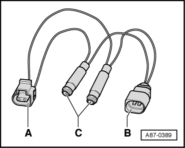
–  Connect the probe -VAS 5051/8- to the adapter leads.
–  Test lead (signal wire) to contact -2- of connector -A-
–  Test lead (screen, earth) to contact -1- of connector -A-
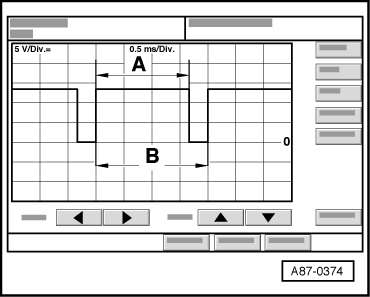
–  On the vehicle diagnostic, testing and information system -VAS 5051 A-, set Measurement mode: DSO (Digital Storage Oscilloscope) and select the setting 5V/div DC, 0.5 ms/div (5 V DC and 0.5 milliseconds per unit)
–  Start the engine.
–  On the operating and display unit, Climatronic control unit -J255-, select „Lo“ temperature setting for driver's and front passenger's side (vehicles with automatically controlled air conditioner).
–  Turn the rotary temperature setting control on the air conditioner controls (air conditioning system control unit -J301-) anti-clockwise as far as the „cold“ stop (vehicles with manually controlled air conditioner).
–  On the operating and display unit, Climatronic control unit -J255-, press the buttons Auto and Off/On or Econ or AC to activate and deactivate actuation of the air conditioner compressor regulating valve -N280- (vehicles with automatically controlled air conditioner).
  Note
Depending on the version of the operating and display unit, „Econ“ mode can be recognised for example from the indicator lamp in the button lighting on the model with ECON button and the indicator lamp in the button not lighting on the model with AC button.
–  On the air conditioner controls (air conditioning system control unit -J301-), press the button AC to activate and deactivate actuation of the air conditioner compressor regulating valve -N280- (vehicles with manually controlled air conditioner).
The display on the oscilloscope screen will be as follows depending on the setting on the operating and display unit, Climatronic control unit -J255-:
–  In „OFF“ or „Econ“ mode („AC off“): No square-wave signal (regulating valve is not actuated)
  A87-0390
–  In „Auto“ mode („AC“ on) and „Lo“ temperature setting (rotary temperature control on „cold“ stop): Square-wave signal with pulse width -A- between 75 % and 100 % (regulating valve is actuated)
  Note
t  The illustration shows a signal with a signal ratio of approx. 80 %.
t  The pulse width -A- is governed by the required cooling output, electrical system voltage etc. (over the width of area -A- the current is controlled via the air conditioner compressor regulating valve -N280- by the operating and display unit, Climatronic control unit -J255- or by the air conditioning system control unit -J301-).
t  The signal distance -B- is always 2 milliseconds (corresponding to a frequency of 500 hertz).
  A87-0374
t  The signal ratio is derived from the ratio of pulse width -A- to signal distance -B-.
–  The setting on the operating and display unit, Climatronic control unit -J255- or on the air conditioning system control unit -J301- and the measured ambient influences govern the pulse width of the square-wave signal (signal ratio between 100 % and greater than 30 %, the regulating valve is actuated such that the compressor output required to obtain the specified temperatures is achieved).
  Note
t  In „Auto“ mode with „Lo“ temperature setting („AC“ on, rotary temperature control on „cold“ stop with manually controlled air conditioner), the air conditioner compressor regulating valve -N280- is actuated such that the maximum permissible current of approx. 0.65 A flows via -N280- (maximum compressor output).
t  In control mode, the actuation time is governed by the required cooling output and the vehicle electrical system voltage, for example. It is however always of sufficient duration to achieve a mean current of 0.3 A.
  A87-0374

Replacing air conditioner compressor pulley > < Detaching air conditioner compressor from holder/attaching (vehicles with 5-cyl. engine)