audi Workshop Repair Guides

Audi Workshop Service and Repair Manuals

Exploded view - gear selector cable and gate selector cable > < Dismantling and assembling selector mechanism
Removing and installing selector mechanism
Removing
–  Remove gear knob together with gear lever boot → Chapter.
–  Remove ashtray in front section of centre console → General body repairs, interior; Rep. Gr.68.
–  Lift out noise insulation above selector mechanism.
   
–  Remove nuts -arrows-.
  A34-0584
–  Remove complete air cleaner housing → Rep. Gr.23 or → Rep. Gr.24.
  A10-10760
–  Detach securing clip -1- for gear selector cable and pull cable off pin.
Metal gate relay lever:
–  Detach securing clip -2- for gate selector cable from gate relay lever and pull cable off pin.
  A34-0620
Plastic gate relay lever:
l  To prevent damage to gate selector cable, cable end-piece must be detached from gate selector cable before removing relay lever.
–  Pull locking mechanism forwards in direction of -arrow 1- onto stop and then turn to left in direction of -arrow 2- to lock.
–  Then press gate relay lever forwards (in direction of -arrow 3-).
l  Detach cable end-piece only when gate relay lever is removed → Fig..
  N34-10891
Continued for all vehicles:
–  Detach cable support bracket from gearbox -arrows-.
  A34-0621
–  Remove front cross member on underbody -arrows-.
  Note
To prevent damage, the flexible joints in the front exhaust pipe must not be bent further than 10°.
–  Disconnect exhaust system at clamp -1-.
  A26-0734
–  Unbolt support bracket for exhaust system -arrows-.
–  Tie up front exhaust pipe on underbody.
  A26-0735
–  Remove rear cross member on underbody -nuts 1 and 2-.
  Note
A second mechanic is required for removing the rear section of the exhaust system.
–  Detach exhaust system at rubber mountings -arrows-.
–  Detach rear silencer at rubber mountings and remove rear section of exhaust system.
  A26-0721
–  Loosen clips -arrows- and remove heat shield together with selector mechanism.
  A34-0585
Installing selector mechanism
Installation is carried out in reverse sequence; note the following:
–  Install selector mechanism and tighten nuts -arrows-. Tightening torque → Item
  A34-0584
–  Route cables -1- from selector mechanism -2- to gearbox as follows:
l  The cables must run parallel and must not be crossed.
l  The cables must be routed in the slot provided in heat shield -3-.
  Note
The enlargement shows the heat shield from above.
  A34-0610
The cables and heat shield are held in the correct positions by clip -A-.
  N34-11247
–  Secure cable support bracket to gearbox -arrows-. Tightening torque → Item
  A34-0621
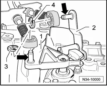
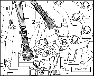
–  Spread a small amount of grease -G 000 450 02- onto pins -arrows- of gearbox selector lever -1- and gate relay lever -2-.
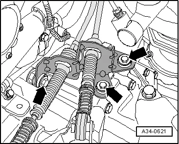
–  Always renew securing clip -3- and, on vehicles with metal gate relay lever -2-, securing clip -4- after removing.
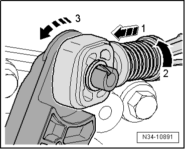
–  Secure gear selector cable with securing clip -3- and gate selector cable with securing clip -4-.
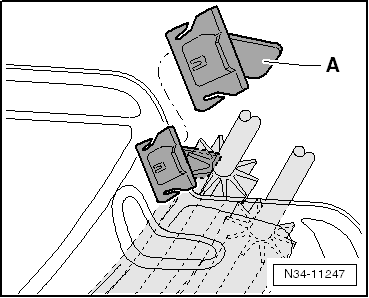
Cable end-piece with plastic gate relay lever
–  You must fit the gate relay lever and the cable end-piece together → Fig..
–  Insert gate selector cable in cable end-piece.
Continued for all selector mechanisms:
–  Adjust selector mechanism → Chapter.
–  Assemble exhaust system and ensure stress-free alignment → Engine, mechanics; Rep. Gr.26.
–  Install complete air cleaner housing → Rep. Gr.23 or → Rep. Gr.24.
–  Install ashtray in front section of centre console → General body repairs, interior; Rep. Gr.68.
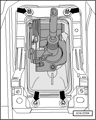
–  Install gear knob together with boot → Chapter.
  N34-10000

Exploded view - gear selector cable and gate selector cable > < Dismantling and assembling selector mechanism