audi Workshop Repair Guides

Audi Workshop Service and Repair Manuals

Transporting gearbox > < Removing gearbox - vehicles with 1.2 ltr. TFSI engine
Removing gearbox - vehicles with 1.4 ltr. TFSI engine
   
Removing gearbox - vehicles with 1.4 ltr. TFSI engine
Special tools and workshop equipment required
t  Support bracket -10 - 222 A-
t  Gearbox support -3282-
t  Adjustment plate -3282/46-
t  Engine and gearbox jack -V.A.G 1383 A-

  Note
All cable ties which are released or cut open during removal must be fitted in the same position when installing.
   
–  Pull off cover for air duct (release retaining clips -arrows- on the sides).
  A10-10367
–  Disconnect hose -1- at air cleaner housing.
–  If fitted, unplug connector -2- at air cleaner housing.
–  Release spring clips -4- and detach air intake hose.
–  Remove bolt -3-.
–  Take out air cleaner housing.
  WARNING
Follow steps required when disconnecting battery → Electrical system; Rep. Gr.27.
  A10-1613
–  Detach cover above battery (press release tab -arrow-).
  A10-10250
–  With ignition switched off, disconnect battery earth strap -arrow-.
  A10-10251
–  Remove battery → Electrical system; Rep. Gr.27.
–  Remove battery tray -arrows-.
  A10-1572
–  Detach coolant hose -1- from engine cover panel.
–  Pull dipstick -2- out of guide tube.
–  Remove engine cover panel -arrows-.
–  Re-insert dipstick -2- in guide tube.
  A10-10950
–  Pull off securing clips -arrow 1- and -arrow 2-.
–  Pull gate selector cable and gear selector cable off joint pins.
–  Pull off securing clip -arrow 3- and remove gate relay lever -B-.
–  Remove nut -arrow 4- and detach gearbox selector lever -A-.
  N34-1820
–  Detach cable support bracket from gearbox -arrows- and place to one side.
  A34-0523
–  Remove clutch slave cylinder -arrows- and place to one side; do not disconnect pipe.
  WARNING
Do not depress clutch pedal after removing slave cylinder.
  A30-0106
–  Unscrew earth wire -1-.
–  Detach electrical wires -2- and -3- at starter and move them clear.
  A10-1577
Vehicles with start/stop system:
–  Unplug connector -arrow- from gearbox neutral position sender -G701-.
  N34-11273
Continued for all vehicles:
–  Remove bolts -1 ... 4- from engine/gearbox flange.
  A34-10486
–  Set up support bracket -10-222 A- on wing mounting flanges.
–  Hook spindle of support bracket into engine lifting eye (left-side).
–  Take up weight of engine with spindle; do not lift.
  A10-10091
–  Remove front left wheel.
–  Remove noise insulation → General body repairs, exterior; Rep. Gr.50.
  A10-10761
–  Remove front section of front wheel housing liner (left-side) → Rep. Gr.66.
  A10-1566
–  Unplug electrical connector -4- for reversing light switch -F4-.
–  Remove nut -arrow- and detach bracket -3- from stud together with electrical wiring -1- and -2-.
–  Remove bolts -arrows- and detach starter.
  A10-10092
–  Remove bolts -1 ... 3- and detach pendulum support.
  A10-1578
–  Unbolt drive shafts (left and right) from gearbox flanges.
–  Tie up drive shafts.
–  Remove engine/gearbox securing bolt -A- above flange shaft (right-side).
  Note
  N34-1825
To prevent damage, the flexible couplings in the front exhaust pipe must not be bent further than 30°.
–  Remove bolts -arrows-.
  A26-0735
–  Remove nuts -1- from exhaust system flange.
–  Unclip Lambda probe wire -arrows-.
–  Detach front exhaust pipe -2- from catalytic converter.
  A34-10463
–  Remove the two bolts -arrows 1- from gearbox mounting.
  N34-1828
–  By adjusting spindle on support bracket -10-222 A-, lower gearbox by distance -a-.
l  Dimension -a- = 60 mm.
  A34-0580
–  Unbolt gearbox bracket from gearbox -arrows 2-.
  N34-1828
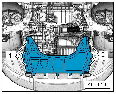
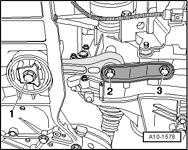
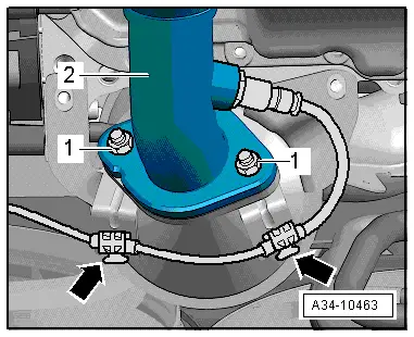
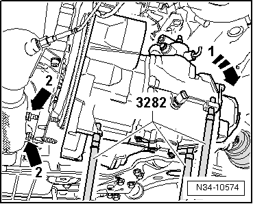
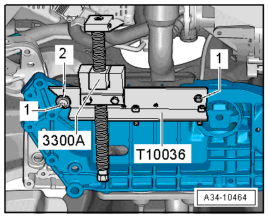
–  Secure support -T10036- to subframe, using two M6x20 bolts -1- and one washer -2-.
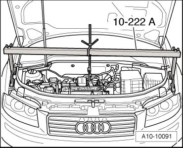
–  Secure engine support -3300 A- and push engine to the front, ensuring that there still is enough clearance to radiator cowl.
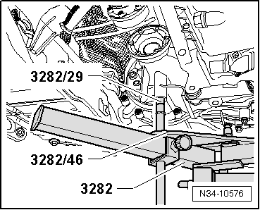
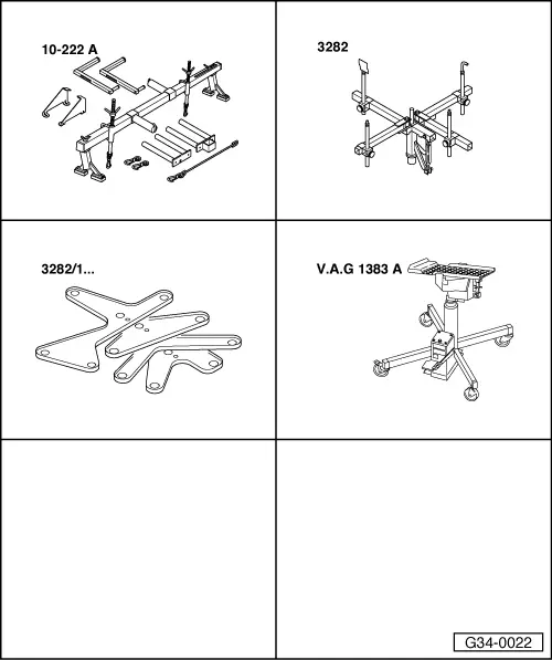
To remove gearbox “0AJ” set up gearbox support -3282- with adjustment plate -3282/46-.
–  Insert gearbox support -3282- in engine and gearbox jack -V.A.G 1383 A-.
–  Place adjustment plate -3282/46- on gearbox support -3282- (adjustment plate only fits in one position).
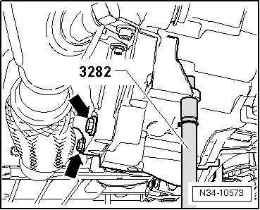
–  Align arms of gearbox support according to holes in adjustment plate.
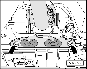
–  Bolt on support elements as illustrated on adjustment plate.
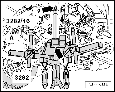
–  Place engine and gearbox jack -V.A.G 1383 A- under vehicle; arrow symbol on adjustment plate points to front of vehicle.
–  Align adjustment plate parallel with gearbox.
Pin -arrow 1- (illustration 10836) should be flush with guide of gearbox support.
  A34-10464
–  Screw pin -3282/29- into hole for bolt securing pendulum support to gearbox.
  N34-10576
–  Secure bolt -3282/45- with a nut M8 to gearbox -arrow 2-.
–  Unscrew engine/gearbox securing bolt -A-.
  N34-10836
–  Remove engine/gearbox securing bolts -arrows- in area of engine sump.
–  Press gearbox off dowel sleeves.
–  Take care not to damage intermediate plate on engine.
–  Carefully push engine towards front (2nd mechanic required).
–  Pivot differential side of gearbox upwards using spindles on gearbox support -3282-.
  N34-10573
–  Turn gearbox in area of cover for 6th gear downwards as illustrated -arrow 1-.
  N34-10574
–  Then carefully guide gearbox with right-hand flange shaft past flywheel/intermediate plate as illustrated -arrow 2-.
–  Lower gearbox, observing subframe at the same time -arrow 1-.
–  When lowering the gearbox, change position of gearbox using the spindles on gearbox support -3282-.
  Note
Pay attention to all pipes/hoses/wiring when lowering gearbox.
  A34-0582

Transporting gearbox > < Removing gearbox - vehicles with 1.2 ltr. TFSI engine