
A3 Mk2
| Removing gearbox (vehicles with 1.8 ltr. TFSI engine) |
| Special tools and workshop equipment required |
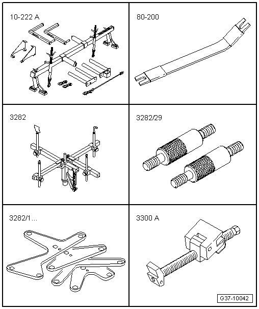
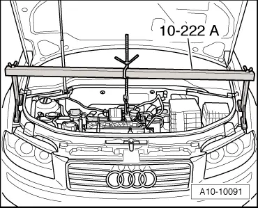
| t | Support bracket -10 - 222 A- |
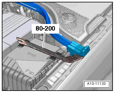
| t | Removal lever -80 - 200- |
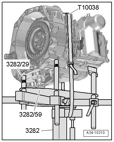
| t | Gearbox support -3282- |
| t | Pin -3282/29- |
| t | Adjustment plate -3282/59- |
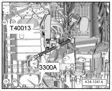
| t | Engine support -3300 A- |
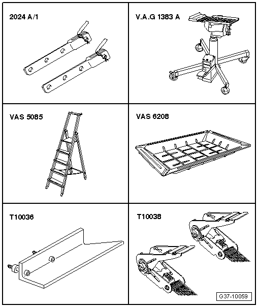
| t | Extension -2024 A /1- |
| t | Engine and gearbox jack -V.A.G 1383 A- |
| t | Stepladder -VAS 5085- |
| t | Drip tray for workshop hoist -VAS 6208- |
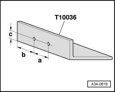
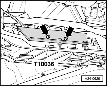
| t | Support -T10036- |
| t | Tensioning strap -T10038- |
 Note
Note
|
|
|
|
|
Note
|
|
|
|
 Caution
|
|
|
|
|
|
|
|
|
|
|
|
|
|
 WARNING
Note
|

|
|
|
Note
|
|
Note
|
|
Note
|
|
Note
|
|
|
|
Note
|
|
|
|
|
|
Note
|
|
|
|
|
|
|
|
|
|
|
|
|
|
|
|
|
|
|
|
|
|
|
|
|
|
|
|
Note
|
|