audi Workshop Repair Guides

Audi Workshop Service and Repair Manuals

Installing gearbox > < Removing gearbox (vehicles with 1.8 ltr. TFSI engine)
Removing gearbox (vehicles with 1.6 ltr. TDI engine)
   
Removing gearbox (vehicles with 1.6 ltr. TDI engine)
Special tools and workshop equipment required
t  Support bracket -10 - 222 A-
t  Removal lever -80 - 200-
t  Gearbox support -3282-
t  Pin -3282/29-
t  Adjustment plate -3282/59-
t  Engine support -3300 A-

   
t  Extension -2024 A /1-
t  Engine and gearbox jack -V.A.G 1383 A-
t  Stepladder -VAS 5085-
t  Drip tray for workshop hoist -VAS 6208-
t  Support -T10036-
t  Tensioning strap -T10038-

Procedure
  Note
t  → Chapter „Repair instructions“.
t  → Chapter „Rules for cleanliness when working on the gearbox“.
t  Observe notes on dual clutch gearbox 0AM → Chapter.
t  Re-attach all cable ties at the same locations when re-installing.
–  Shift selector lever into position „P“.
   
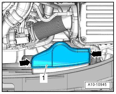
–  Pull off cover -1- for air duct (release retaining clips -arrows- on the sides).
  A10-10945
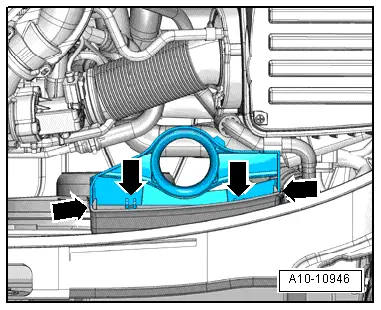
–  Pull off bottom section of air duct (release retaining clips -arrows-).
–  Detach bottom section of air duct with air hose.
  A10-10946
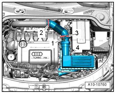
–  Unplug electrical connector -1- from air mass meter -G70-.
–  Remove air hose -2-.
–  Remove bolt -4- and remove air cleaner housing.
  Note
-Item 3- can be disregarded.
  A10-10760
  Caution
When disconnecting the battery there is a risk of serious damage to electronic components:
Observe the correct procedure for disconnecting the battery.
–  Remove battery → Electrical system; Rep. gr.27.
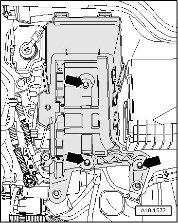
–  Remove bolts -arrows- and detach battery tray.
  A10-1572
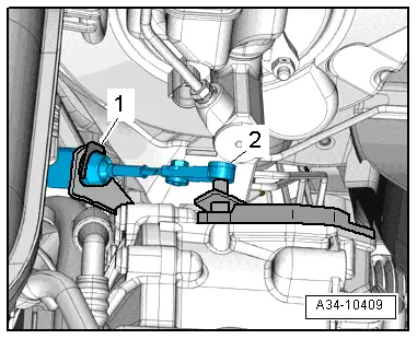
–  Pry selector lever cable -2- off gearbox selector lever using removal lever -80 - 200-.
–  Pull off securing clip -1- for selector lever cable.
  Caution
Risk of damage to selector lever cable.
t  Guide selector lever cable out of cable support bracket when lowering gearbox.
t  Do not bend or kink the selector lever cable.
–  Remove bolts -2- for cable support bracket.
  A34-10409
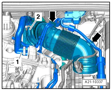
–  Press release tabs and disconnect crankcase breather hose -1- from cylinder head cover.
–  Move clear vacuum hoses -arrows- at air pipe.
–  Release hose clip -2- and detach air pipe.
  A21-10337
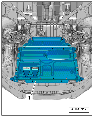
–  Remove noise insulation -1- → Rep. gr.50.
  A10-10917
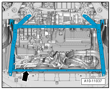
Audi A3 Cabriolet
–  Remove noise insulation frame -arrow- → General body repairs, exterior; Rep. gr.50.
  A10-11037
Continued for all vehicles
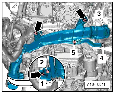
–  Remove bolts -arrows-.
–  Move clear coolant hose at air pipe (left-side).
  Note
-Items 1 ... 5- can be disregarded.
  A19-10641
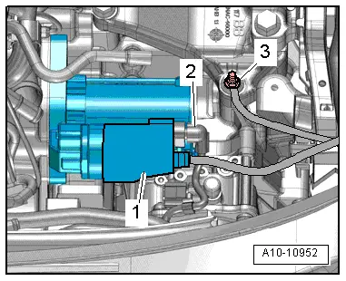
–  Unplug electrical connector -2-.
–  Push back dust boot -1- and disconnect „B+ wire“ from starter solenoid.
–  Remove nut -3- for earth wire.
  A10-10952
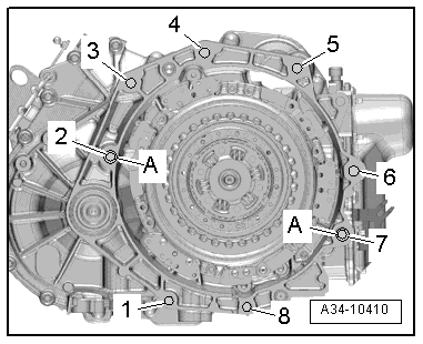
–  Remove bolts -3, 4, 5- securing gearbox to engine.
  A34-10410
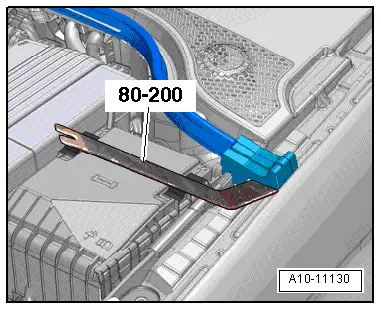
–  Lever clip off sealing element using removal lever -80 - 200- and fold up sealing element.
  A10-11130
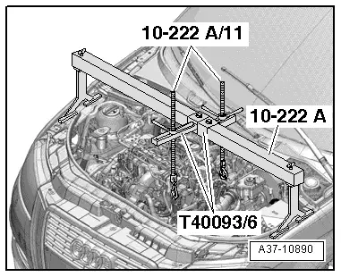
–  Set up support bracket -10 - 222 A- on body flanges, as shown in illustration.
–  Hook spindles of support bracket onto engine lifting eyes.
–  Take up weight of engine with spindles; do not lift.
  WARNING
Risk of scalding from hot steam and hot coolant.
t  The cooling system is under pressure when the engine is hot.
t  Cover filler cap on expansion tank with a cloth and open carefully to release pressure.
–  Open filler cap on expansion tank.
  A37-10890
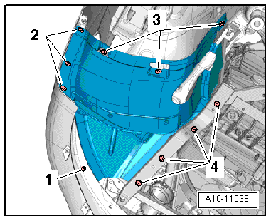
–  Remove both front wheels.
–  Remove front section of front wheel housing liner on both sides → Rep. gr.66.
  A10-11038
  Caution
Risk of irreparable damage to gearbox components.
Never touch the contacts in the gearbox connector with your hands. Static discharge can seriously damage the control unit and mechatronic unit.
–  Touch a suitable earthed object with your hand (without gloves) to discharge any static electricity.
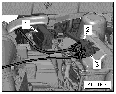
–  Unplug electrical connector -1- for mechatronic unit for dual clutch gearbox -J743-.
–  Take electrical connectors -2- and -3- out of bracket and unplug.
–  Remove all retainers from mechatronic unit for dual clutch gearbox -J743-.
–  Move electrical wiring harness clear on gearbox.
  A10-10953
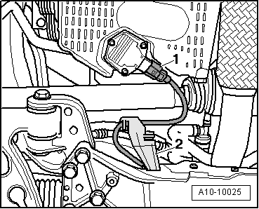
–  Unplug electrical connector -1- at oil level and oil temperature sender -G266-.
–  Unclip bracket -2- for electrical wiring leading to oil level and oil temperature sender -G266- at subframe.
  A10-10025
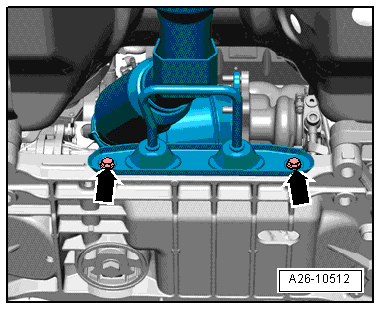
–  Remove bolts -arrows- and pull bracket for exhaust system off pins on front exhaust pipe.
  A26-10512
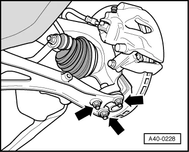
–  Gearbox with flange shafts: unbolt drive shafts (left and right) from gearbox flange shafts → Running gear, front-wheel drive and four-wheel drive; Rep. gr.40.
–  Remove nuts -arrows- securing swivel joint (left and right).
–  If fitted, unscrew nut on bracket for front left vehicle level sender -G78-.
–  Disengage swivel joints from wishbones.
–  Use assembly lever to press drive shafts (left and right) off gearbox.
  A40-0228
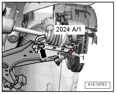
–  Swivel suspension strut (left and right) outwards and support with extension -2024 A /1-, as shown in illustration.
  WARNING
Risk of accident if parts of support are not properly secured.
Secure locking pin and swivel joint with retaining clip -arrow- and nut -1-.
  A10-10763
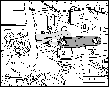
–  Remove bolts -1, 2, 3- and detach pendulum support.
  A10-1578
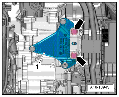
–  Remove bolts -arrows- for assembly mounting on gearbox.
  A10-10949
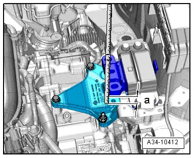
–  Lower engine/gearbox assembly using spindle of support bracket -10 - 222 A- until distance -a- is obtained between gearbox housing and gearbox mounting.
l  Dimension -a- = 40 mm
  A34-10412
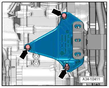
–  Remove bolts -arrows- and detach gearbox support.
  A34-10411
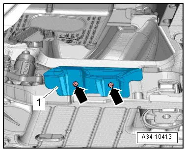
–  Remove bolts -arrows- and detach heat shield -1-.
  A34-10413
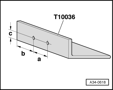
–  Drill two 7 mm diameter holes in support -T10036-, as illustrated.
l  Dimension -a- = 70 mm
l  Dimension -b- = 98 mm.
l  Dimension -c- = 11 mm.
  A34-0618
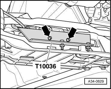
–  Bolt support -T10036- onto subframe with two M6x20 mm bolts -arrows-.
  A34-0629
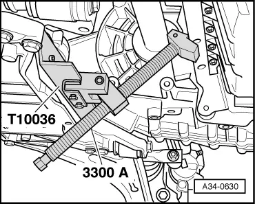
–  Bolt engine support -3300 A- to support -T10036-.
–  Press engine 10 to 15 mm towards front of vehicle using spindle of engine support.
l  Alternator should only make light contact with refrigerant pipe.
l  Air conditioner compressor must not make contact with connection for refrigerant pipe.
  A34-0630
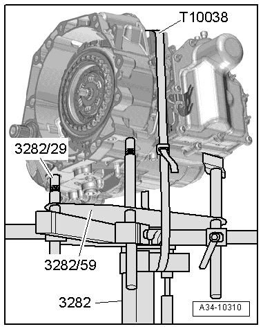
To remove dual clutch gearbox 0AM, set up gearbox support -3282- with adjustment plate -3282/59-.
–  Set up gearbox support -3282- on engine and gearbox jack -V.A.G 1383 A-.
–  Align arms of gearbox support according to holes in adjustment plate -3282/59-.
–  Secure support elements as illustrated on adjustment plate -3282/59-.
–  Place engine and gearbox jack -V.A.G 1383 A- underneath vehicle. The -arrow symbol- on the adjustment plate -3282/42- points in the direction of travel.
–  Align gearbox support -3282- parallel with gearbox.
–  Screw pin -3282/29- into gearbox.
–  Insert last support element in gearbox as illustrated.
–  Use tensioning strap -T10038- to secure gearbox.
–  Support gearbox by lifting from underneath with engine and gearbox jack -V.A.G 1383 A-.
  A34-10310
–  Remove remaining bolts -1, 2, 6, 7, 8- securing gearbox to engine.
–  Press gearbox off dowel sleeves.
–  Pull gearbox off engine.
–  Carefully lower gearbox using engine and gearbox jack -V.A.G 1383 A-.
–  Guide selector lever cable out of cable support bracket while lowering gearbox.
  Note
Do not bend or kink the selector lever cable.
–  While lowering gearbox, change position of gearbox using spindles on gearbox support -3282-.
  A34-10410

Installing gearbox > < Removing gearbox (vehicles with 1.8 ltr. TFSI engine)