
A3 Mk2
| Electrical/electronic components and fitting locations |
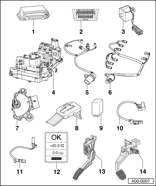
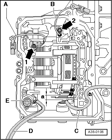
| 1 - | Automatic gearbox control unit -J217- |
| q | Fitting location and removing and installing → Chapter |
| q | Control unit is checked by self-diagnosis |
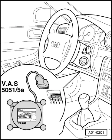
| 2 - | Diagnostic connector |
| q | Fitting location → Fig. |
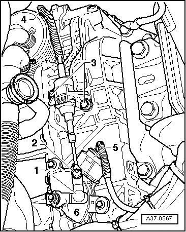
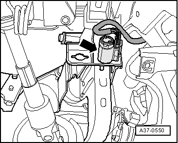
| 3 - | Selector lever lock solenoid -N110- |
| q | Fitting location → Fig. |
| q | Checked via self-diagnosis |
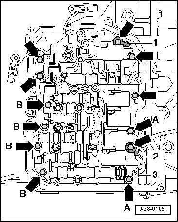
| 4 - | Valve body |
| q | Fitting location → Fig. |
| q | Removing and installing → Chapter |
| q | Identification of solenoid valves → Chapter |
| 5 - | Wiring harness with 8-pin connector and integrated gearbox oil temperature sender -G93- |
| q | Fitting location: the wiring harness is attached to the valve body |
| q | Gearbox oil temperature sender -G93- is checked via self-diagnosis |
| q | Removing and installing → Chapter |
| 6 - | Wiring harness with 14-pin connector |
| q | For solenoid valves and gearbox sensors |
| q | Fitting location: the wiring harness is attached to the valve body |
| q | Designation of solenoid valves and routing of wiring harness → Chapter |
| q | Removing and installing → Chapter |
| 7 - | Multi-function switch -F125- |
| q | Fitting location → Fig. |
| q | Checked via self-diagnosis |
| q | Removing and installing → Chapter |
| 8 - | Selector mechanism cover |
| q | Removing and installing → Chapter |
| q | The tiptronic switch -F189- is integrated in the selector mechanism, fitting location → Fig. |
| 9 - | Starter inhibitor relay -J207- |
| q | Fitting location → Fig. |
| 10 - | Gearbox input speed sender -G182- |
| q | Fitting location → Fig. |
| q | Checked via self-diagnosis |
| q | Removing and installing → Chapter |
| 11 - | Gearbox output speed sender -G195- |
| q | Registers gearbox output speed |
| q | Fitting location → Fig. |
| q | Checked via self-diagnosis |
| q | Removing and installing → Chapter |
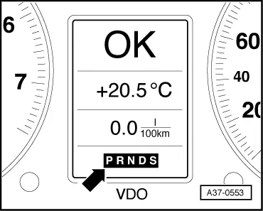
| 12 - | Selector lever position indicator -Y6- |
| q | Fitting location → Fig. |
| q | If selector lever position indicator does not light up, this indicates that gearbox is in emergency running mode with gearbox control unit inactive. |
| q | If all segments of selector lever position indicator light up together, this indicates that gearbox is in emergency running mode with gearbox control unit active. |
| q | Removing and installing → Electrical system; Rep. Gr.90 |
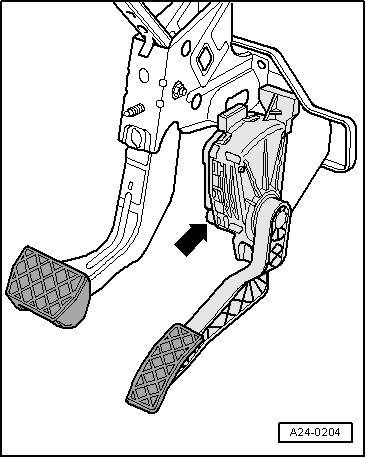
| 13 - | Kickdown switch -F8- |
| q | Fitting location → Fig. |
| q | Checked via self-diagnosis |
| q | Signal transmission from engine control unit to gearbox control unit via CAN bus |
| q | Removing and installing accelerator pedal module → Rep. Gr.20 |
| 14 - | Brake light switch -F- |
| q | Fitting location → Fig. |
| q | Signal transmission from engine control unit to gearbox control unit via CAN bus |
| q | Checked via self-diagnosis |
| q | Removing and installing → Brake system; Rep. Gr.46 |
|
|
|
|
|
|
|
|
|
|
|
|
|
|
|
|
 Note!
Note!
|
|
Note!
|
|