audi Workshop Repair Guides

Audi Workshop Service and Repair Manuals

Checking compression > < Removing and installing cylinder head cover
Removing cylinder head
  Note
t  Renew the cylinder head bolts.
t  On assembly, renew oil seals and gaskets as well as self-locking nuts and bolts that are tightened by turning through to a specified angle.
t  When installing an exchange cylinder head with the camshafts fitted, the contact surfaces between bucket tappet and cam running surface must be oiled after installation of the cylinder head.
t  The plastic protectors fitted to protect the open valves must only be removed immediately before fitting the cylinder head.
t  When fitting a new cylinder head or cylinder head gasket, drain off all the old coolant and re-fill with fresh coolant.
t  Cylinder heads which have cracks between the valve seats or between a valve seat insert and the spark plug thread can be re-installed without reducing service life, provided the cracks are only slight and do not exceed a maximum of 0.3 mm in width, and no more than the first 4 turns of the spark plug threads are cracked.
   
Special tools and workshop equipment required
t  Drip tray for workshop hoist -VAS 6208-
t  Counterhold tool -3036-
t  Two-arm puller -T40001-
t  Puller -T40039-
t  Hose clip pliers -V.A.G 1921-
t  Special wrench (Polydrive) -T10070-

   
t  Support bracket -10 - 222 A-
t  Shackle -10 - 222 A /12-
t  Locking pin -T10060A-
t  Pin wrench -T10020-

Removing
l  Engine in vehicle.
  Note
t  All cable ties which are released or cut open when removing must be refitted in the same position when installing.
t  If engine oil is contaminated, change the oil → Booklet808.
t  Before applying sealant, check information: → Parts catalogue.
–  Obtain code on vehicles with coded radio / radio and navigation system (RNS).
   
–  Lift off engine cover panel -arrows-.
  A10-1709
–  Remove noise insulation (centre) - fasteners -1 ... 3-.
  A10-1565
–  Remove noise insulation (right-side) - fasteners -1 ... 3-.
  WARNING
The fuel system is pressurised. Wrap a cloth around the connection before opening the system. Then release pressure by carefully loosening the connection.
–  Mark fuel supply and return lines.
  A10-1643
–  Detach hose going to activated charcoal filter -1-.
–  Disconnect fuel supply line -2- by pulling release tab.
–  Disconnect fuel return line -3- by pulling release tab.
  A10-1622
–  Disconnect vacuum line -1- going to activated charcoal filter by pressing release tab.
–  Disconnect fuel supply line -2- by pulling release tab.
–  Disconnect fuel return line -3- by pulling release tab.
  A10-1623
–  Lift out activated charcoal filter from retainer with pipes connected -arrow-.
  A10-1581
–  Unbolt bracket -3- for ACF.
–  Unfasten bolt at filler neck of washer fluid reservoir -2-.
–  Disconnect electrical wire for coolant shortage indicator switch at expansion tank -1-.
–  Unbolt coolant expansion tank and lay it aside with pipes connected.
  Note
Before removing, mark direction of rotation of poly V-belt with chalk or felt-tip pen. If the belt runs in the opposite direction when it is refitted, this can cause breakage.
  A13-0646
–  To slacken poly V-belt, turn tensioner in -direction of arrow-.
  A13-0083
–  Lock tensioner in position with locking pin -T10060A-.
–  Take off poly V-belt.
–  Remove locking pin -T10060A- from tensioner for poly V-belt.
  N13-10135
–  Remove the bolts -arrows- and lift off toothed belt cover.
  Note
Engage carefully in toothed belt cover (centre) when installing.
  WARNING
The engine must only be turned at the crankshaft, in the direction of normal engine rotation (clockwise).
  Note
Apply spanner to central bolt of crankshaft for turning engine.
  A13-0558
–  Rotate engine to TDC of No. 1 cylinder by turning central bolt of crankshaft sprocket in normal direction of rotation. Marking on camshaft sprocket and marking on crankshaft must be aligned to TDC of cylinder No. 1 -arrows-.
  A13-0499
–  Position support bracket -10 - 222 A- on bolted flanges of wing panels. The spindles face forwards.
–  Detach crankcase breather hose from oil filler neck.
–  Attach hooks of spindles with shackles -10 - 222 A /12- to the lifting eyes.
–  Take up weight of engine evenly with both spindles (but do not raise engine).
  A10-1645
–  Remove bolts -1- and -2- and detach connecting bracket.
–  Unscrew bolts -3 ... 6- and detach engine mounting.
  A13-0647
–  Unscrew bolts -arrows- and remove engine support.
  Note
To slacken the bolts for the engine support, raise or lower the engine slightly as necessary via the spindles on engine support bracket -10 - 222 A-.
  A13-0559
–  Unbolt crankshaft pulley.
  Note
To loosen and tighten the crankshaft pulley, counterhold central bolt with a ring spanner.
  A13-0356
–  Unbolt toothed belt covers (bottom and centre) -arrows-.
–  Mark rotation direction of toothed belt with chalk or felt-tip pen.
  A13-0557
–  Loosen nut on tensioning roller -arrow- several turns.
–  Remove toothed belt.
  WARNING
Hot steam/hot coolant may escape when opening expansion tank. Cover cap with cloth and open carefully.
–  Open filler cap on coolant expansion tank
  A13-0504
–  Remove cover -1- over battery. To do so, press release tab -arrow-.
  WARNING
Observe notes on procedure for disconnecting battery → Electrical system; Repair group 27.
  A10-1611
–  With ignition switched off, disconnect battery earth cable -arrow-.
–  Place drip tray for workshop hoist -VAS 6208- beneath engine.
  A10-1612
–  Turn drain plug -arrow- on radiator anti-clockwise, if necessary fit drain hose to connection.
  A10-0118
–  Unplug electrical connector -1- from oil pressure sender.
–  Also disconnect bottom coolant hose at coolant pipe -2-, and drain off remaining coolant.
  Note
To avoid damage, the flexible joints in the front exhaust pipe must not be bent more than 10°.
  A19-0391
–  Remove securing nuts -arrows- on front exhaust pipe/exhaust manifold.
  A10-1737
–  Unbolt bracket for exhaust system -arrows-.
  A10-1632
–  Loosen bolt -3-.
–  Unscrew bolts -1- and -2- securing exhaust manifold support (left and right).
  A26-0712
–  Remove exhaust manifold support -arrows-.
–  Use screwdriver to pry off cover caps on wiper arms and unscrew hexagon nuts.
–  Pull wiper arms off wiper shafts and remove.
  A13-0571
–  Unclip washer jets -arrow-.
–  Push washer jets through assembly opening back into plenum chamber, leaving hoses connected.
  A92-0135
–  Pull off rubber seal -1- on plenum chamber cover.
–  Detach plenum chamber cover -2-.
–  Detach engine wiring harness at rear plenum chamber panel.
  A10-1561
–  Remove plenum chamber intermediate plate -arrows-.
  A10-1573
–  Remove electrical connector -1- for Lambda probe (before catalytic converter) from bracket and unplug.
–  Remove electrical connector -2- for Lambda probe (before catalytic converter) from bracket and unplug.
  A10-1614
–  Detach coolant hose -1-.
  A10-1616
–  Disconnect coolant hose -arrow-.
  A10-1618
–  Disconnect coolant hoses -1- and -2- at expansion tank.
  A10-1621
–  Unplug electrical connector -1- for coolant shortage indicator switch at expansion tank.
–  Unscrew coolant expansion tank -arrows- and lay it aside.
  A19-0479
–  Loosen camshaft sprocket bolt using counterhold -3036-.
  A13-0786
–  Detach camshaft sprocket using two-arm puller -T40001- with claws -T40001/6- and -T40001/7-.
  A15-0771
–  Unbolt toothed belt cover (rear) from cylinder head -arrows-.
  A15-0906
–  Disconnect air intake hose -arrow- at bottom of resonator (loosen hose clip using hose clip pliers -V.A.G 1921-).
  A10-1569
–  Detach hose -1- from air cleaner housing.
–  Unplug electrical connector -2- from air cleaner housing.
–  Remove bolt -3-.
–  Disconnect air intake hose -4- from throttle valve unit (loosen hose clip using hose clip pliers -V.A.G 1921-).
–  Take out air cleaner housing.
  A10-1613
–  Unplug electrical connector -arrow- from sender wheel on camshaft.
–  Remove intake manifold → Rep. gr.24.
  A15-0761
–  Disconnect earth cable -2-.
–  Unplug electrical connector -3-.
–  Unplug electrical connector -4-.
–  Remove bolts -1-.
  A13-0561
–  Unplug electrical connectors -2- from ignition coils and move wiring clear.
  A15-0699
–  Remove ignition coils with output stages -2- using puller -T40039-.
–  Loosen cylinder head cover working from outside to inside.
–  Remove cylinder head cover.
  A15-0700
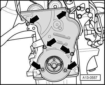
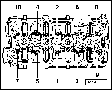
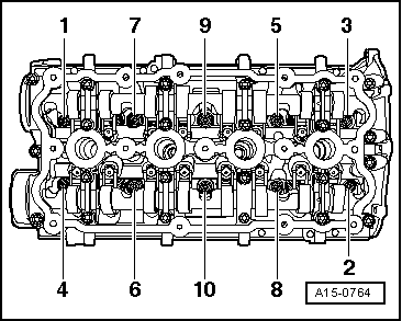
–  Slacken cylinder head bolts using special wrench (Polydrive) -T10070-, keeping to sequence shown.
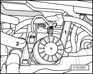
  Note
Check that all hoses, pipes and wiring connections between engine, gearbox and body have been detached.
–  Remove cylinder head.
Installing cylinder head
  Note
t  Renew the cylinder head bolts.
t  On assembly, renew oil seals and gaskets as well as self-locking nuts and bolts that are tightened by turning through to a specified angle.
t  Secure all hose connections with the correct type of hose clips (same as original equipment) → Parts catalogue.
t  If repairing, carefully remove any remaining gasket material from the cylinder head and cylinder block. Ensure that no long scores or scratches are made on the surfaces.
t  Carefully remove any remaining emery and abrasive material.
t  
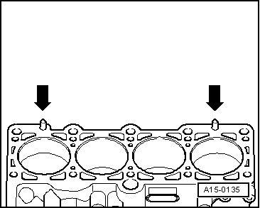
Do not remove new cylinder head gasket from packaging until it is ready to be fitted.
t  Handle gasket very carefully. Damage to the silicone coating or the indented area will lead to leaks.
t  No oil or coolant must be allowed to remain in the blind holes for the cylinder head bolts in the cylinder block.
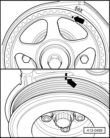
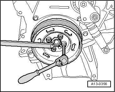
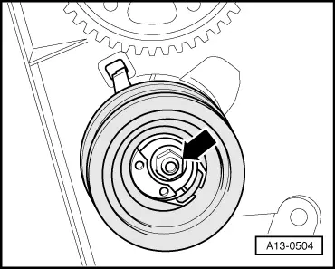
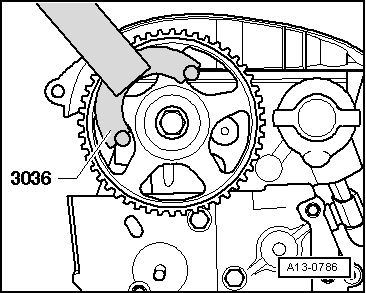
t  For high-temperature paste refer to → Parts catalogue.
  WARNING
The engine must only be turned at the crankshaft, in the direction of normal engine rotation (clockwise).
  Note
Apply spanner to central bolt of crankshaft for turning engine.
  A15-0764
–  Set camshaft to TDC for No. 1 cylinder before fitting cylinder head -arrow-.
–  Check whether crankshaft is at No. 1 cylinder TDC -bottom arrow-.
  A13-0499
–  Place cylinder head gasket in position.
t  Note position of centring pins in cylinder block -arrows-.
t  Note installation position of cylinder head gasket. Part No. should be legible from inlet side.
–  Fit cylinder head.
–  Insert and hand-tighten cylinder head bolts.
  A15-0135
–  Tighten cylinder head bolts in two stages in sequence shown as follows:
–  Tighten using torque wrench:
t  1st stage: 40 Nm
–  Tighten using rigid spanner:
t  2nd stage: turn 180° (1/2 turn) further (alternatively 2 x 90° is possible)
  Note
Cylinder head bolts do not have to be torqued down again later after repair work.
–  Install cylinder head cover → Chapter.
–  Install wiper arms → Electrical system; Rep. Gr. 92.
–  Install toothed belt: engine codes AXW, BMB, BHD → Chapter, engine codes BLX, BLY, BLR, BVY, BVZ → Chapter.
–  Install poly V-belt → Chapter.
–  Electrical connections and routing → Current flow diagrams, Electrical fault finding and Fitting locations.
–  Install intake manifold → Motronic direct injection and ignition system (4-cylinder); Rep. Gr. 24; Servicing injection system.
–  Connect battery → Electrical system; Rep. Gr. 27.
–  Bleed fuel system → Motronic direct injection and ignition system (4-cylinder); Rep. Gr. 24; Servicing fuel injection system.
–  Check oil level.
–  Fill up with coolant → Chapter.
  Note
t  Drained-off coolant may only be used again if the original cylinder head and cylinder block are re-installed.
t  Contaminated or dirty coolant must not be used again.
  WARNING
Never use battery charging equipment for boost starting. There is danger of damaging the vehicle's control units.
Tightening torques
  A15-0767
Component Nm
Bolts/nutsM610
 M820
Except for the following:  
Front exhaust pipe to exhaust manifold25 1)2)
Cylinder head cover to cylinder head10
Toothed belt cover to cylinder block10 3)
Battery cable clamp to battery terminal6

l  1 Coat exhaust manifold studs and Lambda probe threads with high-temperature paste; for high-temperature paste refer to → Parts catalogue.
l  2) Renew nuts/bolts.
l  3) Install using locking fluid; for locking fluid refer to → Parts catalogue.
   

Checking compression > < Removing and installing cylinder head cover