
A3 Mk2
|
|
|
|
|
 WARNING
|
|
|
|
|
|
|
|
|
|
|
|
|
|
|
|
|
|
|
|
 Note
Note
|
|
|
|
| Component | Nm | ||
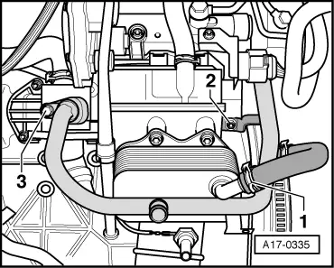
| Coolant pipe to cylinder block | 10 | ||
| Coolant pipe to thermostat housing | 10 | ||
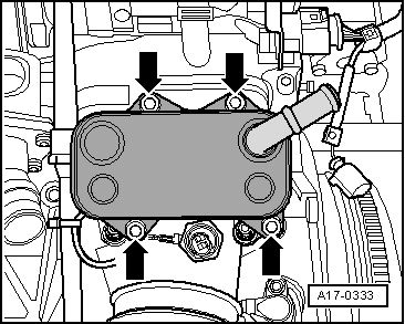
| Oil cooler to oil filter bracket | 25 | ||
| Oil filter housing to cylinder block | 22 | ||