audi Workshop Repair Guides

Audi Workshop Service and Repair Manuals

Assembly mountings > < Securing engine to engine and gearbox support
Installing engine
Installing engine
Procedure
l  Engine attached to engine bracket -T10012-
Installation is carried out in the reverse order; note the following:
  Note
t  Renew self-locking nuts and bolts when performing assembly work.
t  Renew bolts which are tightened to a specified angle as well as oil seals and gaskets.
t  Reinstall all cable ties in the same locations when assembling.
t  Secure all hose connections with the correct type of hose clips (same as original equipment) → Electronic parts catalogue.
t  Clean input shaft splines and (in the case of used clutch plates) the hub splines. Remove corrosion and apply only a very thin coating of grease for clutch plate splines -G 000 100- to the splines. Then move clutch plate back and forth on input shaft until the hub moves smoothly on the shaft. Remove any excess grease.
t  Tightening torques apply only to lightly greased, oiled, phosphated or black-finished nuts and bolts.
t  Additional lubricant such as engine oil or gearbox oil may be used, but do not use lubricant containing graphite.
t  Do not use degreased parts.
t  Tolerance for tightening torques: ± 15 %.
–  Check whether dowel sleeves for centring the engine/gearbox assembly are fitted in the cylinder block; install if necessary.
   
–  Make sure that intermediate plate is engaged on sealing flange -arrow A- and pushed onto dowel sleeves -arrows B-.
Vehicles with manual gearbox:
–  Check that clutch plate is correctly centred → Rep. gr.30.
–  Check clutch release bearing for wear; renew if necessary.
–  Bolt gearbox to engine.
  A13-10521
Securing engine to manual gearbox
  A37-0214
ItemBoltNm
1, 2M12x6580
3 1), 4 1)M12x13580
5 … 7M10x6040
8M12x9065
ADowel sleeves for centralising
l  1) Bolt with M8 threaded pin

   
–  Push in deflector plate -2- in such a way that the lower lug engages into the cylinder block and secure on top with bolt -1-.
  Note
Shown in illustration with gearbox removed.
  A34-0234
Vehicles with automatic gearbox:
Checking installation depth of torque converter:
If the torque converter has been correctly installed, the distance between the contact surfaces at the bottom of the studs on the torque converter and the joint surface on the torque converter bell housing (with automatic gearbox) -a- is at least 19.5 mm.
  Caution
If the torque converter is not installed correctly, the drive lugs of the torque converter and the ATF pump will be seriously damaged when the gearbox is joined to the engine.
  A32-0013
Securing engine to automatic gearbox
  A37-0751
ItemBoltNm
1, 2M12x5580
3 1)2), 4 1)2)M12x16580
5M10x6540
6, 7M10x5540
8M12x10065
ADowel sleeves for centralising
l  1) Bolt with M8 threaded pin
l  2) Bolt also secures starter to gearbox

   
–  To secure torque converter on drive plate, use only new nuts -arrow- of the correct type (same as original equipment), as specified in → Electronic parts catalogue.
  Note
Disregard -item 1-.
  A37-0678
Securing engine to dual clutch gearbox
  A34-10477
ItemBoltNm
1, 3M12x5580
2M12x17080
4M12x8080
5, 6, 7M10x5040
8M12x9065
ADowel sleeves for centralising

   
All vehicles (continued):
–  Guide engine/gearbox assembly into the body.
–  Tighten bolts -arrows- of assembly mounting for engine initially hand-tight.
  A10-1642
–  Tighten bolts of assembly mounting for gearbox -arrows- initially hand-tight.
–  Use new securing bolts.
  Note
The bolts are tightened to final torque only after adjusting the assembly mountings → Chapter.
–  Remove engine bracket -T10012- from engine.
  A10-1634
–  Apply locking fluid to sealing plug -arrow- and insert plug.
t  Locking fluid → Electronic parts catalogue
  A10-1639
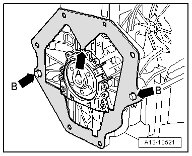
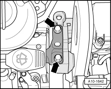
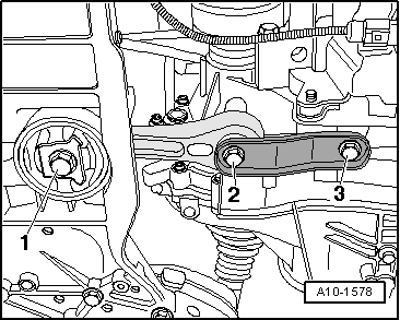
–  Secure pendulum support with bolts -1 ... 3- to gearbox and subframe.
–  Install drive shafts → Rep. gr.40.
–  Install front exhaust pipe with catalytic converter: vehicles with engine codes BGU, BSE, BSF, CCSA → Chapter.
–  Install front exhaust pipe with catalytic converter: vehicles with engine code CMXA → Chapter.
–  Align the exhaust system so it is free of stress → Chapter.
–  Install air conditioner compressor → Rep. gr.87.
–  Install slave cylinder for hydraulic clutch mechanism → Rep. gr.30.
–  Attach and adjust selector mechanism at manual gearbox → Rep. gr.34.
–  Attach and adjust selector lever cable → Rep. gr.34 or → Rep. gr.37.
–  To facilitate positioning of alternator, drive back bushes for securing bolts slightly.
–  Install alternator → Rep. gr.27.
–  Install poly V-belt → Chapter.
–  Adjust engine mountings → Chapter.
–  Electrical connections and routing → Current flow diagrams, Electrical fault finding and Fitting locations.
–  Install battery → Rep. gr.27.
–  Install wiper arms → Rep. gr.92.
–  Bleed fuel system → Rep. gr.24.
–  Check engine oil level → Booklet808.
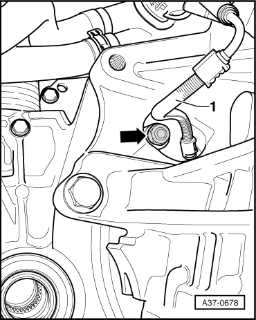
–  Connect coolant hose with plug-in connector to radiator → Fig..
–  Fill cooling system → Anchor.
  Note
t  Drained coolant may not be used again if the cylinder head or cylinder block have been renewed.
t  Contaminated or dirty coolant must not be used again.
  Caution
Never use battery charging equipment for boost starting. There is danger of damaging the vehicle's control units.
–  Check ATF level of automatic gearbox → Rep. gr.37.
Tightening torques
  A10-1578
ComponentNm
Bolts/nutsM610
 M715
 M820
 M1040
 M1265
Except for the following: 
Torque converter to drive plate57 1)
Sealing plug in cylinder block10 2)
Pendulum support to:Gearbox40 + 90° 1)3)
Subframe100 + 90° 1)3)
Air-conditioner compressor to bracket for ancillaries25
Terminal B+ to starter16
Earth wire to gearbox23
l  1) Renew nuts/bolts.
l  2) Apply locking fluid when installing; refer to → Electronic parts catalogue for locking fluid.
l  3) 90° = one quarter turn.


Assembly mountings > < Securing engine to engine and gearbox support